
Air burst to clear detection window

a detection window and air burst technology, applied in the direction of cleaning process and equipment, chemistry apparatus and processes, vacuum cleaners, etc., can solve the problems of affecting the measurement/monitoring, affecting the measurement/monitoring, affecting the view and light of the measurement/monitoring target, etc., to prevent the accumulation of particulates

Active Publication Date: 2012-02-09
HONEYWELL INT INC
View PDF13 Cites 34 Cited by
  • Summary
  • Abstract
  • Description
  • Claims
  • Application Information

AI Technical Summary

Benefits of technology

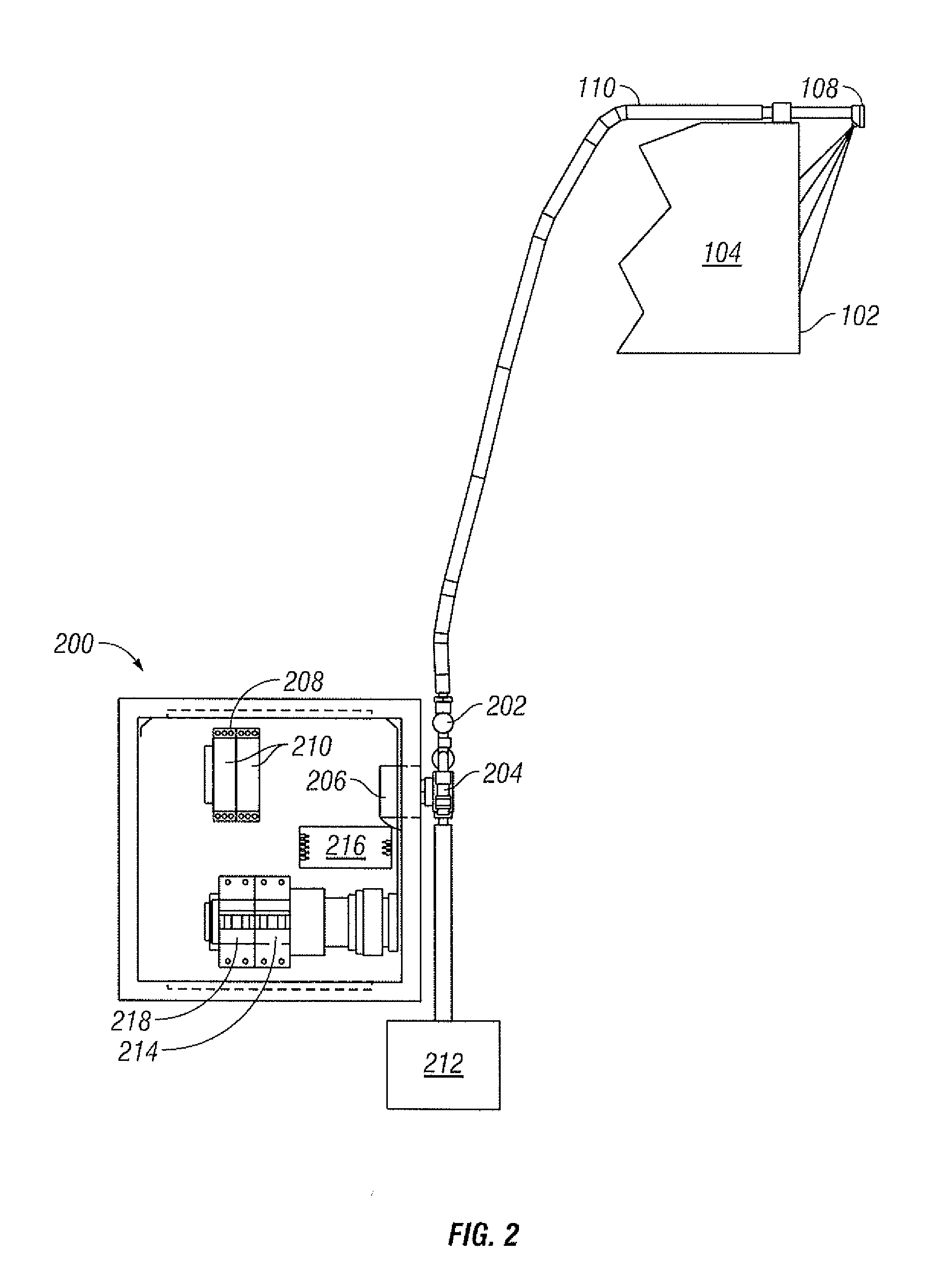
[0010]Additionally, a compressed air source can provide compressed air to an air control solenoid. A timer module directs a magnetic valve of a support box to supply power to the coil of the air control solenoid in order to engage the solenoid. When the air control solenoid is engaged, compressed air is provided to an air burst nozzle. The air burst nozzle directs a burst of air at a window of a housing to clear it of any particulates. In accordance with user programming of the timer module, the process can then be repeated at regular intervals or upon user demand. In an alternative embodiment, an air knife nozzle can be configured and utilized to prevent accumulation of particulates on the window.

Problems solved by technology

Particularly in process environments, the window and light source are susceptible to becoming obscured when dust, moisture, and other contaminants collect on the window and light the surface of the source.
A dirty window or light source, for example, can gradually affect the measurement / monitoring results and, ultimately, block the view and light with respect to the measurement / monitoring target.
Thus, optical measuring / monitoring devices and systems require periodic manual cleaning, which is expensive and, in some cases, difficult or impossible to arrange.
Tissue manufacturing machines utilized in optical / monitoring applications, for example, present some unique challenges with respect to maintaining a clear sharp picture and optimal lighting due to the amount of fiber dust generated by the machine in normal operation.
For example, a disadvantage of wiper blades and water sprays is that such components can block a user's view for a short period of time, thus preventing proper measurement / monitoring.
Additionally, a washing system that utilizes water can exacerbate the situation by transforming the fiber dust into a paste that can then accumulate, and eventually require extensive cleaning.
A pinhole, utilized in the context of tissue manufacturing machines, is typically configured as a small hole without a window, which requires highly specific and costly pinhole optics.
Additionally, air knives typically generate turbulent airflow, which does not fully protect the window from particulate accumulation.
The standard air knife can be successful in keeping a majority of the dust away from the lens or window, but due to static charge build-up on the glass and dead area under the wipe, eventually dust does build up and obscures the view.

Method used


Image

  • Air burst to clear detection window
  • Air burst to clear detection window
  • Air burst to clear detection window

Examples


Embodiment Construction

[0015]It is to be understood by persons of ordinary skill in the art that the following descriptions are provided for purposes of illustration and not for limitation. An artisan understands that there are many variations that lie within the spirit of the invention and the scope of the appended claims. Unnecessary detail of known functions and operations may be omitted from the current description so as not to obscure the present invention.

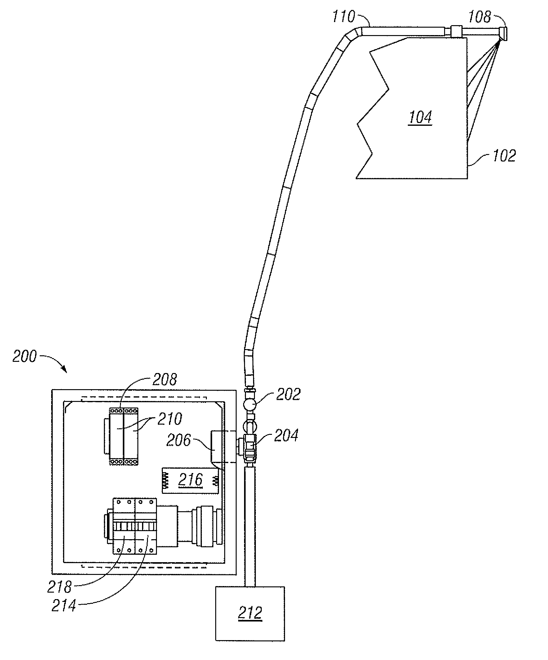
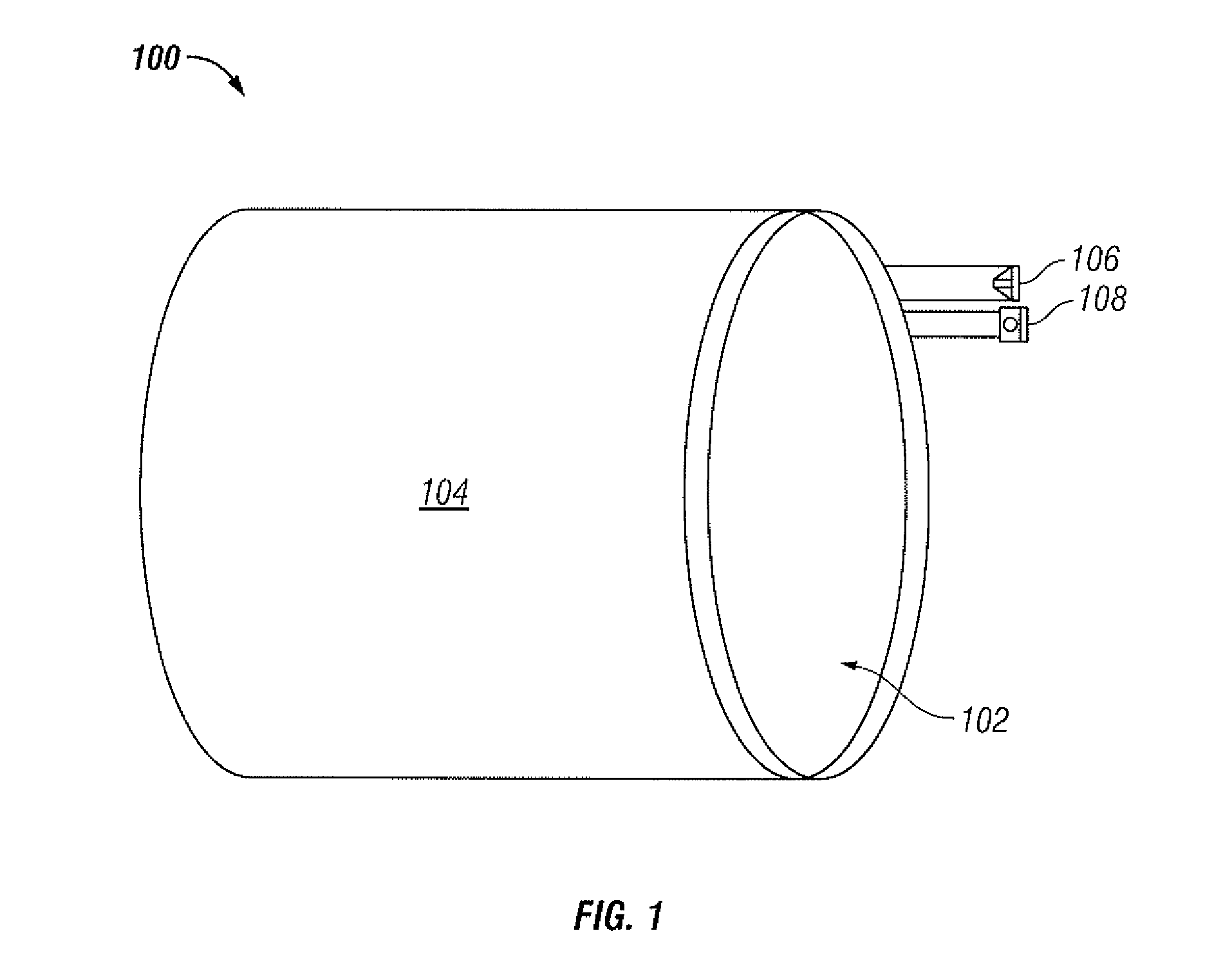
[0016]FIG. 1 illustrates a front view of an apparatus 100 for deploying a burst of air to clear particulates from a surface, in accordance with the disclosed embodiments. The apparatus 100 includes a housing 104 having a window 102 through which an optical sensing device (not shown) can “view” a monitoring / measuring target. A lighting device may also be positioned within the housing 104 such that light is directed out from behind the window to illuminate the area being monitored / measured. The housing 104 protects the optical sensing / lighting device...


PUM


Abstract

An apparatus including a housing having at least one window, an air burst nozzle positioned atop the housing and aimed at the window, a compressed air source, an air control solenoid connected to the air burst nozzle, the compressed air source, and a support box. The compressed air source provides compressed air to the air control solenoid. A timer module directs a magnetic valve of the support box to supply power to the coil of the air control solenoid in order to engage the solenoid. When the air control solenoid is engaged, compressed air is provided to the air burst nozzle. The air burst nozzle directs a burst of air at the window of the housing to clear it of any particulates. In accordance with user programming of the timer module, the process is then repeated at regular intervals.

Description

TECHNICAL FIELD[0001]Embodiments are generally related to optical measuring and monitoring applications. Embodiments are further related to systems and methods for clearing particulates from a surface.BACKGROUND OF THE INVENTION[0002]Optical measuring and monitoring applications generally require a window from the detection apparatus to the measurement / monitoring target. In addition, optical monitoring / measuring requires sufficient lighting to function properly. Particularly in process environments, the window and light source are susceptible to becoming obscured when dust, moisture, and other contaminants collect on the window and light the surface of the source. A dirty window or light source, for example, can gradually affect the measurement / monitoring results and, ultimately, block the view and light with respect to the measurement / monitoring target. Thus, optical measuring / monitoring devices and systems require periodic manual cleaning, which is expensive and, in some cases, di...

Claims


Application Information

Patent Timeline
IPC IPC(8): B08B5/02
CPCB08B5/02
Inventor MANNINEN, KEIJOMATILAINEN, TEEMUHAZA, JAMES
Owner HONEYWELL INT INC
Learn More