Shift hydraulic control circuit of dual-clutch gearbox

A clutch control, dual clutch technology, applied in transmission control, components with teeth, belts/chains/gears, etc., can solve the problems of complicated shift control scheme, inability to adapt to small cars, difficult design and manufacture of valve blocks, etc. , to achieve the effect of simplifying the shifting hydraulic control system of the dual-clutch transmission, easy design and manufacture, and reducing the complexity

Active Publication Date: 2010-05-19
CHONGQING TSINGSHAN IND
View PDF3 Cites 35 Cited by
  • Summary
  • Abstract
  • Description
  • Claims
  • Application Information

AI Technical Summary

Problems solved by technology

The scheme of dual-clutch clutch shift control directly affects the performance, cost and implementation of the system. In the existing hydraulic shift control system of dual-clutch automatic transmission, the odd-numbered clutches and the even-numbered clutches are respectively controlled by two independent solenoid valves. However, the shift control schemes are relatively complicated. For example, in patents US2006005647 and US20060009326A1, two-stage hydraulic control is used in the shift pressure control circuit. First, the odd circuit (first gear, third gear) is obtained through two pressure control valves gear, 5th gear, N gear) and dual circuits (2nd gear, 4th gear, 6th gear, R gear), and then divide the two pressure oil circuits into 4 oil circuits through 4 ON / OFF switch valves, and then pass The shift control valve controlled by the solenoid valve transmits the pressure to the corresponding piston pressure control chamber. The system has many solenoid valves and complex structure, and the system cost is quite high.
The complex system also makes the design and manufacture of the valve block difficult, and the volume is large, which cannot be used on small cars.

Method used


Image

  • Shift hydraulic control circuit of dual-clutch gearbox
  • Shift hydraulic control circuit of dual-clutch gearbox
  • Shift hydraulic control circuit of dual-clutch gearbox

Examples


Embodiment Construction

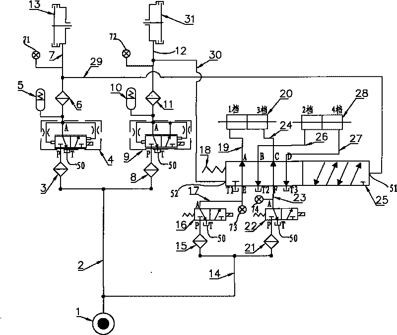
[0019] Such as figure 1 As shown, the first embodiment of the hydraulic control circuit for shifting of the dual-clutch gearbox of the present invention includes a clutch pressure control circuit for controlling the action of the dual clutch, two two-position three-way solenoid valves 16, 22 for shifting and one shifting The shift hydraulic circuit that controls the action of the shift oil cylinder is composed of the multi-way valve 25, and the shift multi-way valve 25 is controlled by the pressure control device to make it actuate.

[0020] In the clutch pressure control circuit, the dual clutches are odd clutches 13 and even clutches 31. One end of the clutch main oil passage 2 is connected to the main oil source 1, and the other end is connected to the first filter 3 and the second filter 8 respectively. The outlet of the filter 3 is connected with the oil supply port P of the two-position three-way solenoid valve 4 of the odd clutch through the pipeline, and the oil return...


PUM


Abstract

The invention provides a shift hydraulic control circuit of a dual-clutch gearbox, comprising a shift hydraulic circuit which is constituted by two shift two-position three-way electromagnetic valves and a shift multiway valve and which controls the action of a shift cylinder, and the movement of the shift multiway valve is controlled by the pressure control device. Compared with the shift hydraulic pressure circuit in the prior art, the circuit of the shift magnetic valve in the invention has selectivity, can reduce the usage amount of the electromagnetic valve by a half and can obviously reduce the complexity degree of the hydraulic system; the combination of the clutch hydraulic circuit, the two shift two-position three-way electromagnetic valve, the shift multiway valve and the pressure control device greatly simplifies the dual-clutch gearbox shift hydraulic pressure control system, optimizes the hydraulic circuit, leads the design and manufacturing of the valve block to be easier, lowers the system cost, leads the volume of the valve block to be small and is suitable for the use requirement of coupes.

Description

technical field [0001] The invention relates to a hydraulic control circuit, in particular to a gear shift hydraulic control circuit of a dual-clutch gearbox. Background technique [0002] The clutch and shift control of the dual-clutch automatic transmission is the core control part of the dual-clutch automatic transmission. Due to the stable control performance of the wet multi-disc clutch, large heat capacity, mature and convenient hydraulic control, and good control performance, it is obtained in the dual-clutch automatic transmission system. a wide range of applications. The scheme of dual-clutch clutch shift control directly affects the performance, cost and implementation of the system. In the existing hydraulic shift control system of dual-clutch automatic transmission, the odd-numbered clutches and the even-numbered clutches are respectively controlled by two independent solenoid valves. However, the shift control schemes are relatively complicated. For example, in...

Claims


Application Information

Patent Timeline
Patent Type & Authority Applications(China)
IPC IPC(8): F16H61/00F16H61/28F16H61/688
Inventor 周勇游同生斯红路彭飞刘国京
Owner CHONGQING TSINGSHAN IND
Why Eureka
Try Eureka