Directional Mobile Antenna with Polarization Switching by Displacement of Radiating Panels

a mobile antenna and polarization switching technology, applied in the direction of leaky waveguide antennas, linear waveguide fed arrays, antennas, etc., can solve the problems of affecting adjacent communication systems, bulky and expensive antennas, and severe restrictions to be adhered to by these antennas

Active Publication Date: 2013-10-24
THALES SA
View PDF1 Cites 32 Cited by
  • Summary
  • Abstract
  • Description
  • Claims
  • Application Information

AI Technical Summary

Benefits of technology

[0010]The expression tracking antenna is understood to mean an antenna able to maintain its pointing at a given target (for example a satellite), by compensating for the movements of the craft on which it is installed. The antenna according to the invention thus makes it possible to switch its polarization whilst keeping it pointing at the same target.
[0014]The swivel axis, termed the first swivel axis, may be mounted on a second swivel axis orthogonal to the said first swivel axis. According to a first embodiment, the first axis makes it possible to orient the antenna in elevation, the second axis making it possible to orient the antenna in azimuth. According to another embodiment, the first axis makes it possible to orient the antenna in azimuth, the second axis making it possible to orient the antenna in elevation.

Problems solved by technology

The constraints to be adhered to by this antenna are severe.
The reflector, with a diameter of about 60 to 70 cm, must thus benefit from a considerable freedom of movement and from a reliable and precise control system, thus leading to bulky and expensive antennas.
Furthermore, the radiating elements of a beamforming antenna must be sufficiently close together to avoid the formation of lateral radiation lobes, liable to perturb adjacent communication systems.
However, it comprises drawbacks.
Indeed, its structure imposes a relatively large distance between the radiating elements, thereby giving rise to overly sizable lateral lobes in the radiation pattern.
However, the proposed structure is not adapted to the tracking of pointing.

Method used


Image

  • Directional Mobile Antenna with Polarization Switching by Displacement of Radiating Panels
  • Directional Mobile Antenna with Polarization Switching by Displacement of Radiating Panels
  • Directional Mobile Antenna with Polarization Switching by Displacement of Radiating Panels

Examples


Embodiment Construction

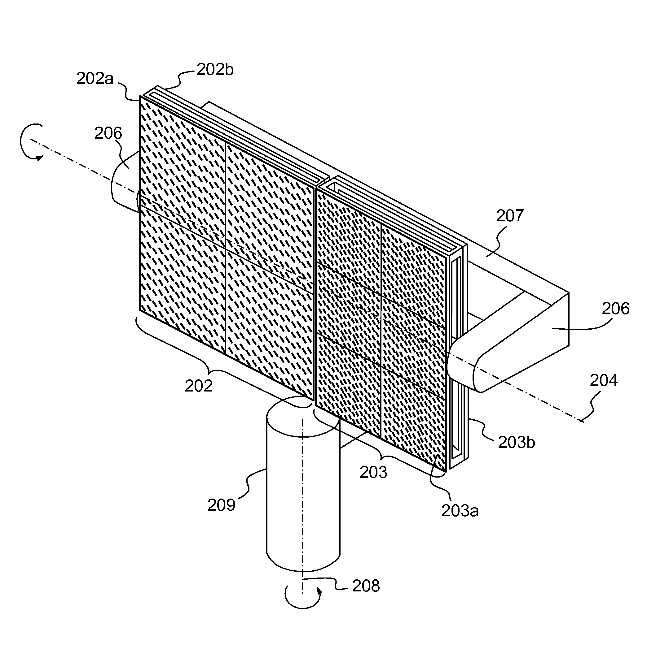
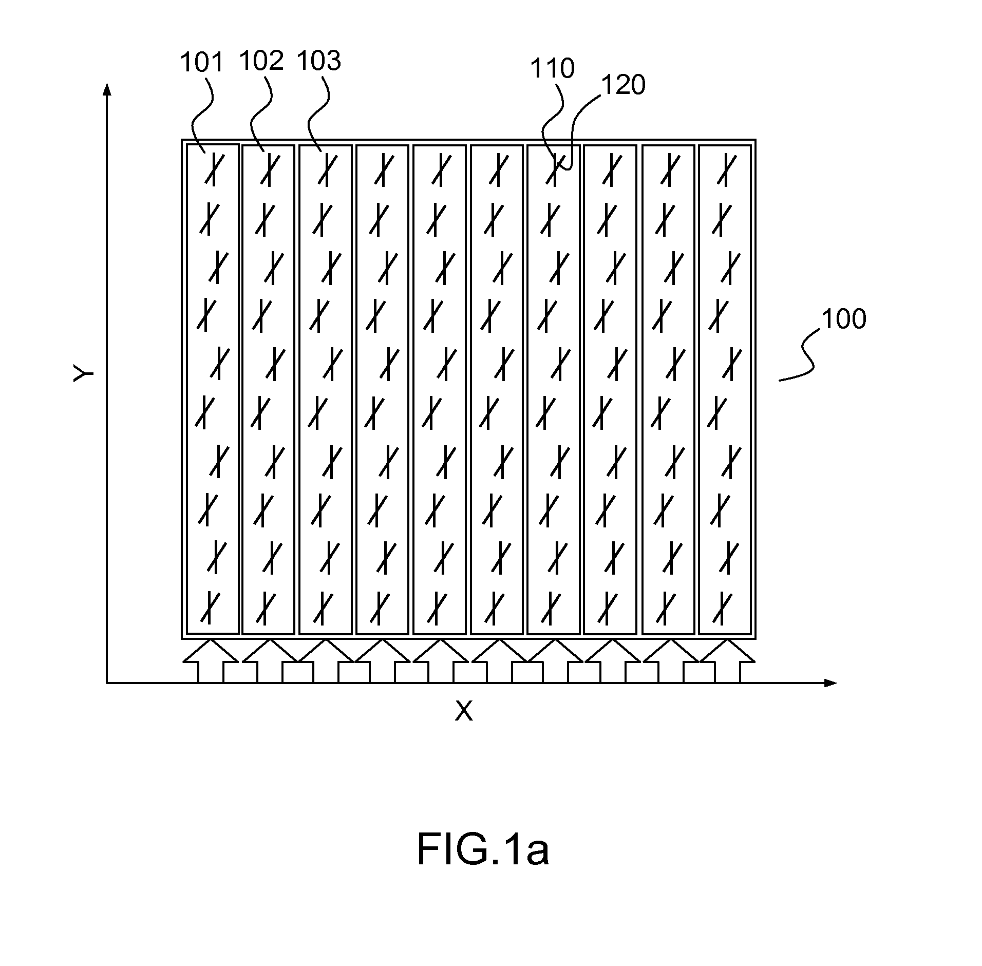
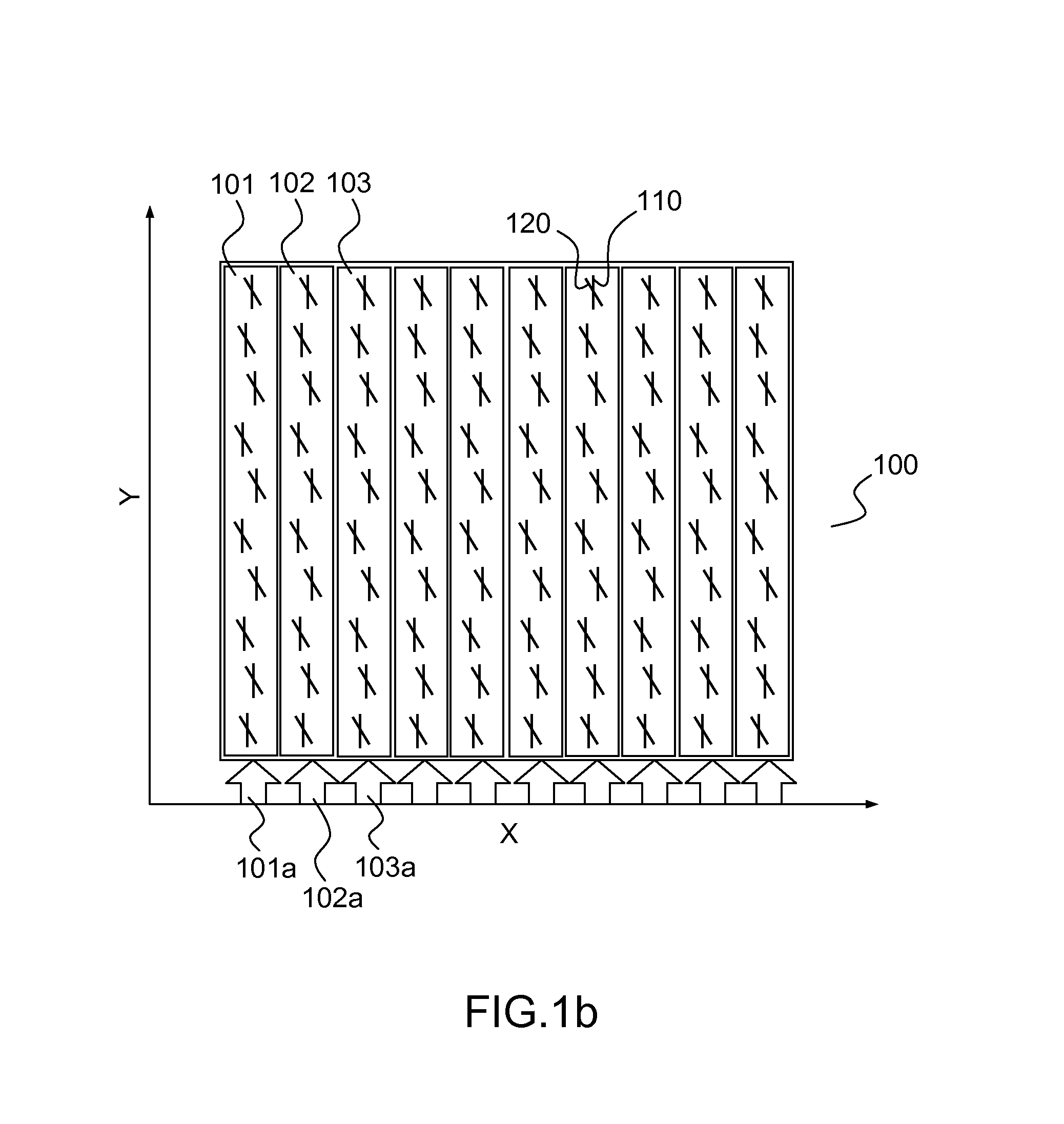
[0025]FIGS. 1a and 1b illustrate by basic diagrams the antenna according to the invention. The antenna 100 is viewed from above. Each of the waveguides 101, 102, 103 is fed with radiofrequency signals 101a, 102a 103a and extends parallel to the Y axis. The waveguides may be guides with rectangular cross-section. Each waveguide 101, 102, 103 is regularly drilled with apertures 110 in the form of rectangular slots preferably parallel to the waveguide. By way of example, the antenna occupies an area of about 6 cm×6 cm.

[0026]A radiating element 120 in the form of a dipole is placed above each aperture 110, in a plane parallel to the plane in which the apertures 110 are made. The plane in which the dipoles are placed is advantageously situated at a distance equal to a value chosen between a fifth and a quarter of the wavelength of the signals transmitted in the waveguides, in order to produce such a perturbation on the field coming from the aperture so that two orthogonal field component...


PUM


Abstract

An antenna with polarization switching comprises a support comprising at least two faces each supporting a plurality of waveguides fed with radiofrequency signals and pierced with apertures disposed so as to illuminate radiating elements placed some distance from the said apertures. For at least one given antenna pointing, the said support is able to toggle between at least two different configurations, the said support being configured so as to place, in the second configuration, the second face in a position identical to that taken by the first face in the first configuration, several radiating elements of the first face being, in the said position, oriented differently from radiating elements of the second face. It applies notably to the switching of antennas embedded onboard moving objects on the ground having to operate high-speed communications with a satellite, in particular a geostationary satellite.

Description

CROSS-REFERENCE TO RELATED APPLICATION[0001]This application claims priority to foreign French patent application No. FR 1201170, filed on Apr. 20, 2012, the disclosure of which is incorporated by reference in its entirety.FIELD OF THE INVENTION[0002]The present invention relates to a mobile directional plane antenna able to switch its polarization by displacement of radiating panels. It applies notably to the switching of antennas embedded onboard moving objects on the ground having to operate high-speed communications with a satellite, in particular a geostationary satellite.BACKGROUND[0003]In order to provide for communications between a fixed point, for example a geostationary satellite, and a moving point, for example a vehicle on the ground, an antenna making it possible to hunt down the fixed point is disposed at the level of the moving object. The constraints to be adhered to by this antenna are severe. Notably, it must be configured so as not to emit in other directions sig...

Claims


Application Information

Patent Timeline
Patent Type & Authority Applications(United States)
IPC IPC(8): H01Q15/24
CPCH01Q15/246H01Q13/22H01Q21/005H01Q21/245
Inventor LENORMAND, REGISHIRSCH, ANTONINMARTINEAU, PATRICKHERRANZ- HERRUZO, JOSE IGNACIOVALERO-NOGUERIA, ALEJANDROVINCENT, PAULDAVID, JEAN-FRANCOISLABORDE, LAURENCE
Owner THALES SA
Why Eureka
Try Eureka