Apparatus and Method for Spatially Referencing Images

Active Publication Date: 2013-10-24
GOOGLE LLC
View PDF7 Cites 76 Cited by
  • Summary
  • Abstract
  • Description
  • Claims
  • Application Information

AI Technical Summary

Benefits of technology

[0008]Some aspects include a camera for acquiring spatially-referenced images of indoor spaces. The camera may include one or more cameras each having an optical axis, a camera mount coupled to the cameras and configured to align the optical axes with a plurality of generally radially symmetric directions, each of the radially symmetric directions approximately corresponding to an angular field of view of the cameras, one or more laser range finders each coupled to a corresponding one of the cameras and each oriented approximately parallel to the optical axis of the corresponding one of the cameras, an orientation sensor coupled to the cameras and configured to indicate which of the radially symmetric directions each of the cameras is facing, one or more processors communicatively connected to the laser range finders and the cameras, and memory communicatively connected to the processors. The memory may store instructions that when executed by the processors cause the following to occur: storing images captured by the cameras in the memory; storing distances measured by the laser range fi

Problems solved by technology

In some systems and some use cases, it is difficult to determine the location from which an image is captured within an indoor space.
Indoor spaces are typically more challenging to spatially reference than outdoors, where location is often determined based on global positioning satellite signals or based on the wireless environment.
But indoors, these location-indicating signals are often attenuated, impeding efforts to identify the location from which an image is captured.
And other techniques for identifying the location of images within an indoor space are often expensive.
For example, the location of a camera may be measured relative to some reference point by manually measuring d

Method used


Image

  • Apparatus and Method for Spatially Referencing Images
  • Apparatus and Method for Spatially Referencing Images
  • Apparatus and Method for Spatially Referencing Images

Examples


Embodiment Construction

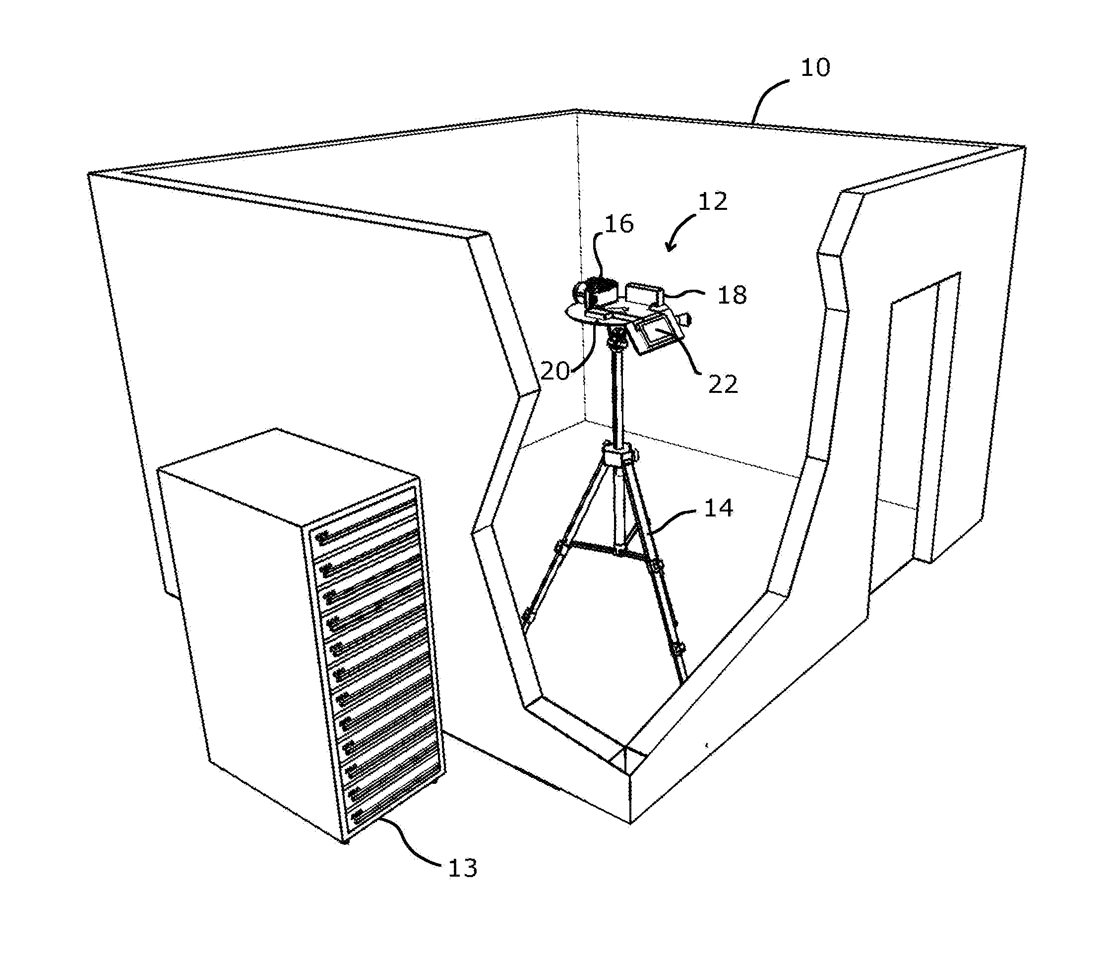
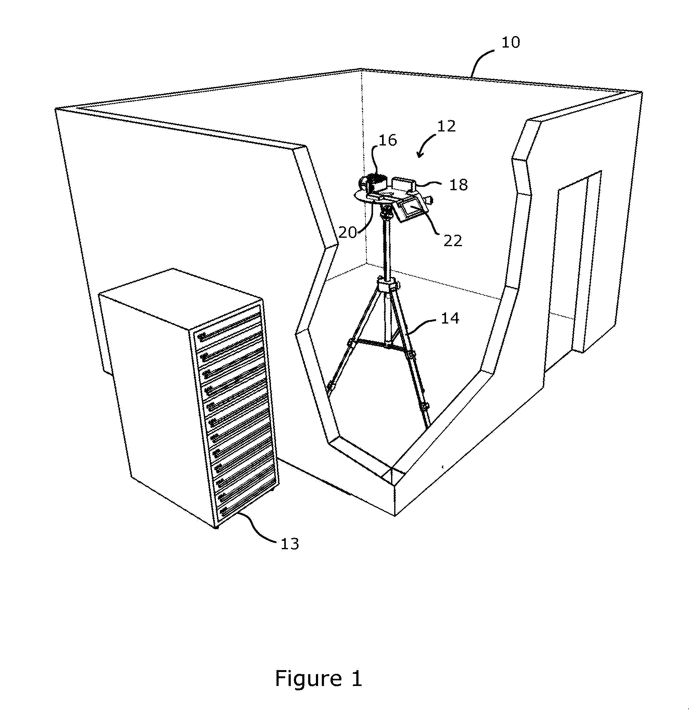
[0021]FIG. 1 illustrates an embodiment of an indoor space 10, a distance-referencing camera 12 for acquiring distance-referenced images of an indoor space, and a tour server 13. (Tour server 13 is depicted near the camera 12 in FIG. 1, but in many applications, would be geographically distant.) In some embodiments, as explained further below, the distance-referencing camera 12 may be configured to obtain panoramic images of the interior of indoor spaces and to obtain data indicative of the locations from which the panoramic images are captured. As explained below, the data indicative of the locations from which the panoramic images are captured may be acquired with relatively little effort and using relatively inexpensive hardware.

[0022]In some instances, the distance-referencing camera 12 may be configured to obtain, for each panoramic image (“panorama”), a relatively small number of distance measurements of the distance between the distance-referencing camera 12 and the walls of t...


PUM


Abstract

Provided is a method of spatially referencing a plurality of images captured from a plurality of different locations within an indoor space by determining the location from which the plurality of images were captured. The method may include obtaining a plurality of distance-referenced panoramas of an indoor space. The distance-referenced panoramas may each include a plurality of distance-referenced images each captured from one position in the indoor space and at a different azimuth from the other distance-referenced images, a plurality of distance measurements, and orientation indicators each indicative of the azimuth of the corresponding one of the distance-referenced images. The method may further include determining the location of each of the distance-referenced panoramas based on the plurality of distance measurements and the orientation indicators and associating in memory the determined locations with the plurality of distance-referenced images captured from the determined location.

Description

BACKGROUND OF THE INVENTION[0001]1. Field of the Invention[0002]The present invention relates generally to cameras and, more specifically, to techniques for spatially locating images from cameras based on distance measurements to features in the images.[0003]2. Description of the Related Art[0004]Often, users of electronic devices, such as personal computers and smart phones, wish to view on their electronic device the interior of a building or other man-made or natural structure that establishes an indoor space. For example, a device user may wish to view on their device the interior of a store that they are considering visiting, a cave that they are considering exploring, a facility that they are considering renting, or a room about which they are curious, e.g., a room in an art gallery or a museum. Users also often desire to see different views from different locations within these and other indoor spaces. Seeing the indoor space from different perspectives generally provides the...

Claims


Application Information

Patent Timeline
IPC IPC(8): G06T7/60G01C11/02H04N13/20
CPCG06T7/602G01C11/02G06T2207/10012G06T7/593G06T7/68H04N13/20G06F18/22H04N23/698G01C11/025G06T17/00G06T2207/30244
Inventor STARNS, ALEXANDER T.RAMAN, ARJUNROYZ, GADI
Owner GOOGLE LLC
Why Eureka
Try Eureka