Flash light device
- Summary
- Abstract
- Description
- Claims
- Application Information
AI Technical Summary
Benefits of technology
Problems solved by technology
Method used
Image
Examples
Embodiment Construction
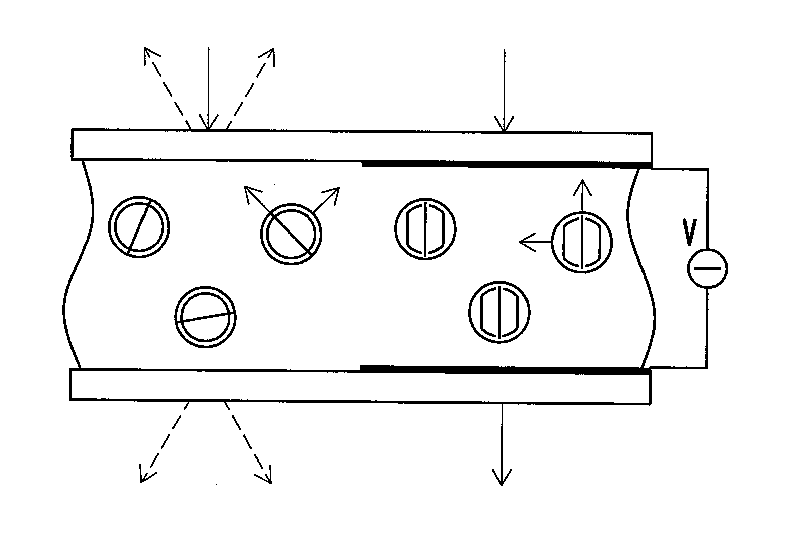
[0032]FIG. 3 is a schematic diagram of a flash light device according to an embodiment of the invention. Referring to FIG. 3, a flash light device 300 includes a light diffuser 301, a light diffuser's driving unit 302, a light source 311 and a light source's driving unit 312.
[0033]The light diffuser's driving unit 302 is coupled to the light diffuser 301 and receives a set of voltage information 5303. The set of voltage information 5303 indicates a plurality of driving voltages S304 required by the light diffuser 301. The light diffuser's driving unit 302 produces the driving voltages S304 and apply the driving voltages S304 with a certain control timing to the light diffuser 301. The light source's driving unit 312 is coupled to the light source 311 and receives a trigger signal S313 so as to adjust the time for the light source 311 to produce flashing or the flash intensity.
[0034]The light diffuser 301 herein includes a plurality of sub-blocks (as shown by FIG. 3, W00-W45). Each o...
PUM
| Property | Measurement | Unit |
|---|---|---|
| Time | aaaaa | aaaaa |
| Electric potential / voltage | aaaaa | aaaaa |
Abstract
Description
Claims
Application Information
 - R&D
- Intellectual Property
- Life Sciences
- Materials
- Tech Scout
- Unparalleled Data Quality
- Higher Quality Content
- 60% Fewer Hallucinations
Browse by: Latest US Patents, China's latest patents, Technical Efficacy Thesaurus, Application Domain, Technology Topic, Popular Technical Reports.
© 2025 PatSnap. All rights reserved.Legal|Privacy policy|Modern Slavery Act Transparency Statement|Sitemap|About US| Contact US: help@patsnap.com


