Apparatus and method of foam dyeing a traveling sheet of textile yarn

a textile yarn and foam dyeing technology, applied in the direction of dyeing process, textile treatment by spraying/projecting, application, etc., can solve the problem of difficult, if not impossible, to coat the entire surface of each yarn without leaving undyed streaks, and achieve the effect of deepening the color shad

Inactive Publication Date: 2013-10-31
GASTON SYST INC
View PDF2 Cites 5 Cited by
  • Summary
  • Abstract
  • Description
  • Claims
  • Application Information

AI Technical Summary

Benefits of technology

[0005]An added advantage of the present invention is that the dye applied by the different applicators can be the same as or different in concentration or color or type of dye from the dye or shade of dye applied in the other applicators. Using the same dye in all the applicators results in a deepening of the shade of the color imparted by the dye. Using dyes of different colors in various applicators results in selected color variations in the yarns and in the resulting fabric woven or knitted from the yarns. Having the centers undyed while the surfaces are dyed allows color fashioning in a woven fabric made from those dyed yarns, which is particularly of interest in denim fabrics, such as used for manufacturing fashionable blue jeans.
[0006]Dividing of a traveling sheet of yarn into separate spaced sheet portions is known in the slashing art where the spaced separate yarns are fed into two different sizing boxes, but this has not involved foam dyeing and particularly foam applicators located between divided yarn sheets to apply foamed dye to the inner facing surfaces of the opposite divided yarn sheets.
[0007]Briefly described, in one form, the preferred embodiment of the present invention provides an apparatus and method for dyeing a traveling sheet of textile yarns with dye applied in a foam condition. A pair of driven infeed nip rollers feeds the yarn in a downstream direction, and a pair of outwardly spaced guide rollers downstream of the infeed rollers guide the yarn sheet in separated spaced portions. A pair of driven yarn sheet recombining nip rollers is located downstream of the outwardly spaced rollers for recombining the separated yarn sheet portions

Problems solved by technology

A problem with the prior art apparatuses and methods is that the mass of yarns in the traveling sheet are crowded together and tend to overlap or otherwise become entangled with adjacent yarns,

Method used


Image

  • Apparatus and method of foam dyeing a traveling sheet of textile yarn
  • Apparatus and method of foam dyeing a traveling sheet of textile yarn
  • Apparatus and method of foam dyeing a traveling sheet of textile yarn

Examples


Embodiment Construction

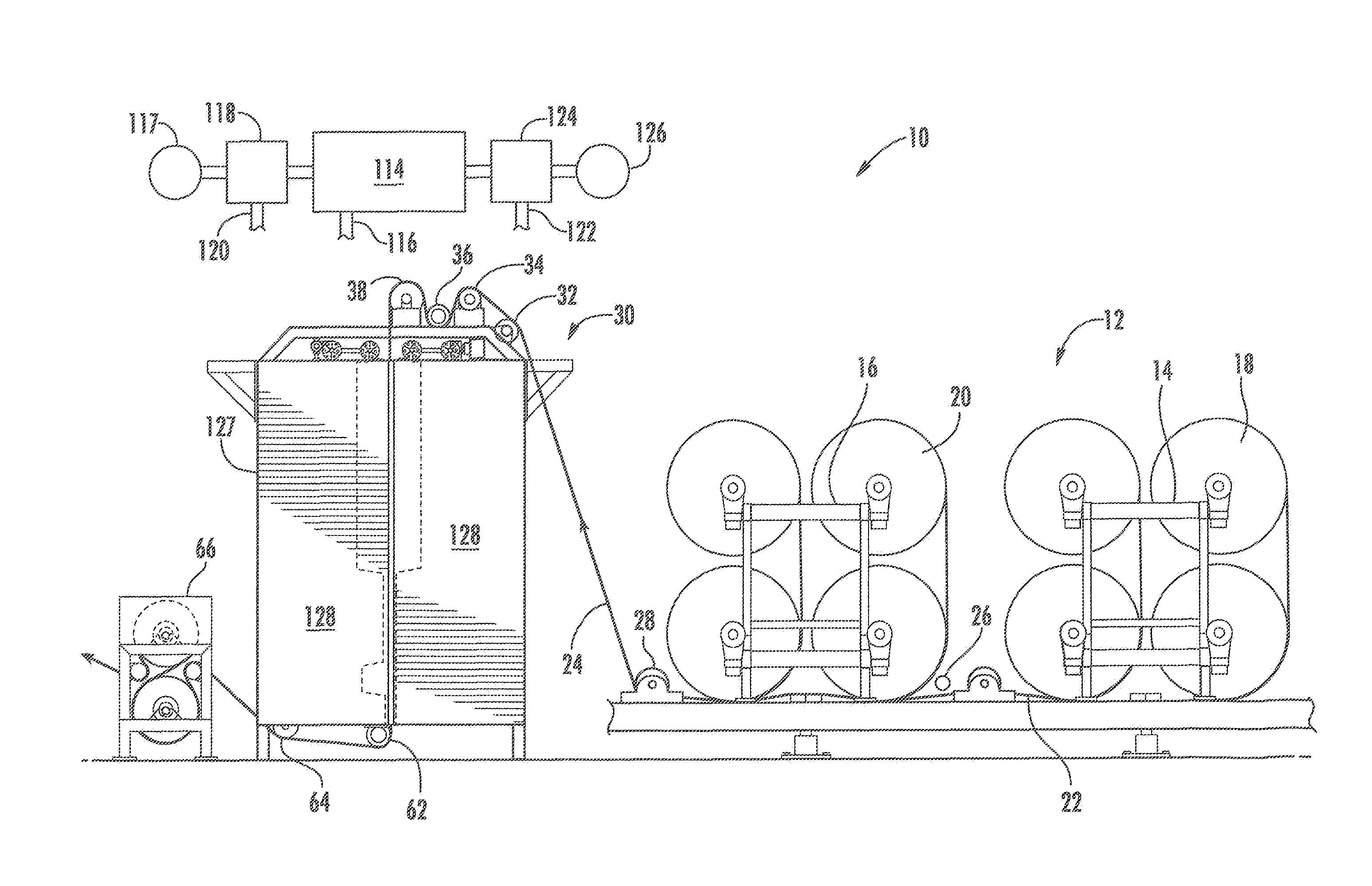
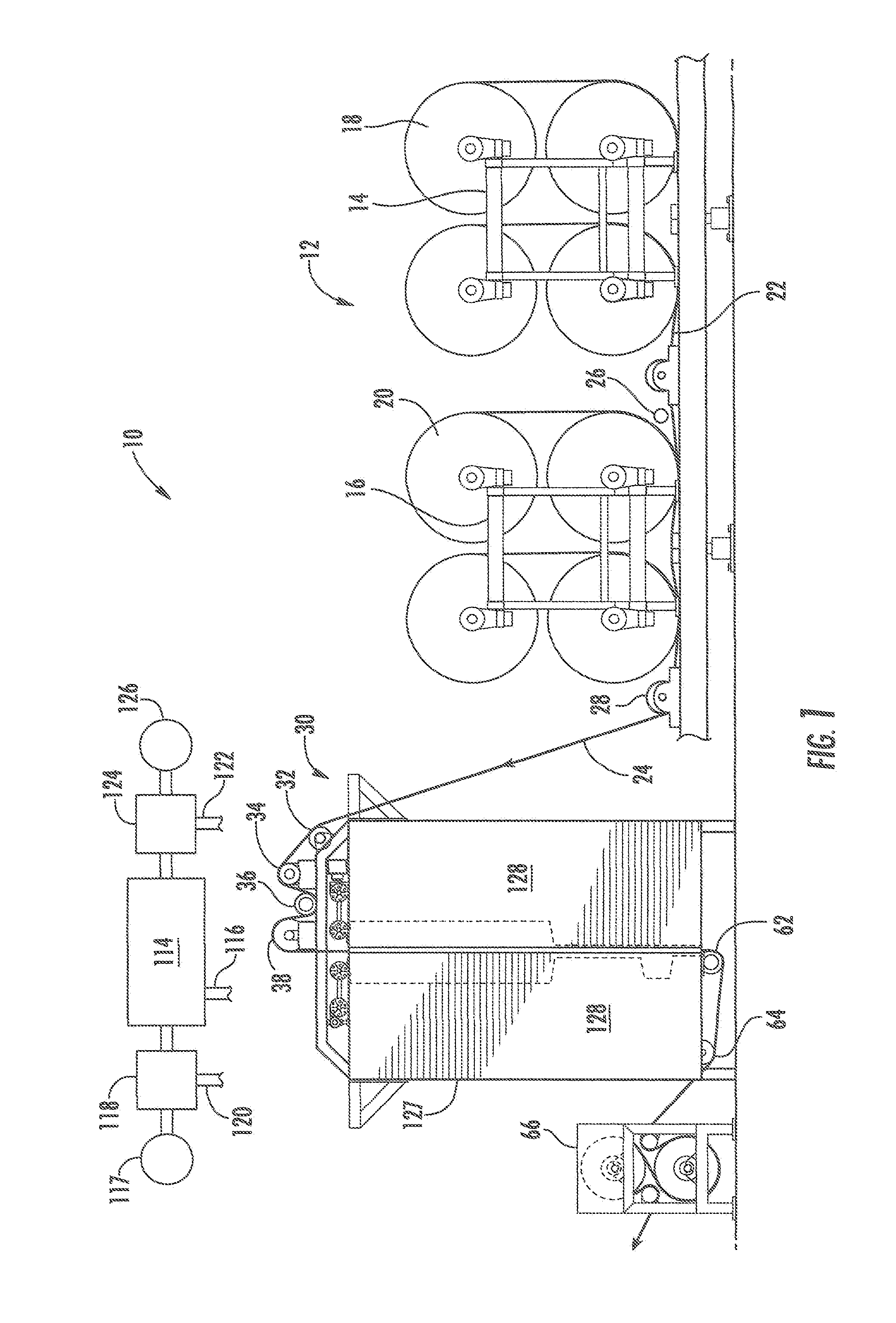
[0017]The dyeing apparatus 10 of the preferred embodiment of the present invention illustrated in the accompanying drawings, feeds originally undyed cotton yarns that are wound on warp beams 12 supported in two racks, 14 and 16, arranged in series with each rack supporting four warp beams 18 and 20 in a two over two stacking arrangement. One rack 14 is outboard of the other rack 16. Yarns from the four beams 18 of the outboard rack 14 are withdrawn and combined into a single yarn sheet 22 that passes under the beams 20 of the inboard rack 16 and combined with the yarns drawn from the beams 20 of the inner rack 16 to form a combined single sheet 24 drawn from the eight warp beams.

[0018]In threading up the apparatus 10, a cross yarn 26 is laid across the top of the sheet 22 of yarns from the outboard rack 14 prior to the sheet passing under the beams 20 of the inner rack 16. In this manner, the yarns from the inner rack 16 are laid on top of the cross yarn 26 in combining with the yar...


PUM

PropertyMeasurementUnit
Densityaaaaaaaaaa
Dyeing enthalpyaaaaaaaaaa

Abstract

Dyeing a traveling sheet of textile yarn with a dye in foamed condition, and, more particularly, dyeing by separating a traveling sheet of yarn into separate spaced portions and applying foamed dye to the inner facing and outer facing surfaces of the yarns in the spaced portions. Then recombining the spaced portions into a single sheet and further applying foamed dye to the yarn in the recombined sheet.

Description

FIELD OF THE INVENTION[0001]Dyeing a traveling sheet of textile yarn with dye in foam condition, and more particularly, dyeing by separating a traveling inner sheet of yarn into separate spaced portions and applying foam and dye to the inner facing and outer facing surfaces of the yarns in the spaced portions, then recombining the spaced portions into a single sheet and further applying foam guide to the yarns in the recombined sheet.BACKGROUND OF THE INVENTION[0002]It is known to use foamed dye to dye textile substrates by applying multiple coats of dye in a foamed state sequentially on traveling textile substrates using spaced foam applicators on opposite sides of the traveling substrates. One such prior art apparatus and method developed by the assignee of the present invention has a vertical series of spaced pairs of opposed foam applicators that apply foam to opposite sides of a traveling cotton textile substrate. In the specific embodiment of the prior art illustrated in the a...

Claims


Application Information

Patent Timeline
IPC IPC(8): D06P1/96D06B1/02
CPCD06B1/08D06B11/002D06B19/0094
Inventor AURICH, CHRISTOPH W.
Owner GASTON SYST INC
Why Eureka
Try Eureka