
Building panels of solid wood

a technology of building panels and solid wood, applied in the field of building panels, can solve the problems of reducing the content of building panels, affecting the construction efficiency of buildings, and affecting the construction efficiency of buildings, and achieve the effect of high toughness

Active Publication Date: 2013-10-31
VÄLINGE INNOVATION AB
View PDF10 Cites 35 Cited by
  • Summary
  • Abstract
  • Description
  • Claims
  • Application Information

AI Technical Summary

Benefits of technology

This patent is about building panels made of solid wood that have a special locking system. The locking system is designed to work well in different weather conditions and to prevent any gaps or cracks when the climate changes from wet to dry. The panels can be used for flooring and are very durable and stable. The panels can be made from different species of wood and can be locked together with a tension force applied. The locking strip is made of the same material as the panels, which allows for a smooth and secure locking. Overall, this patent describes a new and improved way to produce durable and stable wood panels that are resistant to changes in climate.

Problems solved by technology

A drawback with the known building panels that are provided with a mechanical locking system is that a gap may arise between two adjacent building panels which are locked together, when the moisture content of the building panels decreases.
The mechanical locking system may also break down due to an asserted tension load that is caused by the decrease of the moisture content.
The shrinkage and the swelling of the building panels create a problem since gaps between two adjacent and assembled building panels may arise when the building panels shrink.
Thus, the problems with gaps with respect to solid wood products are greater.
When the building panels shrink, the locking strip locks two adjacent and assembled building panels together, and consequently a tension load is asserted on the locking strip.
Commonly used hard wood species, such as oak, are brittle.
The shrinking and swelling mentioned above may also result in gaps forming between a wall and floorboards assembled in a floating manner.

Method used


Image

  • Building panels of solid wood
  • Building panels of solid wood
  • Building panels of solid wood

Examples


Embodiment Construction

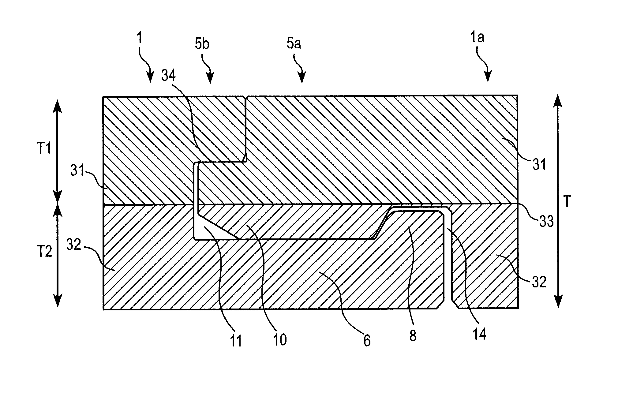
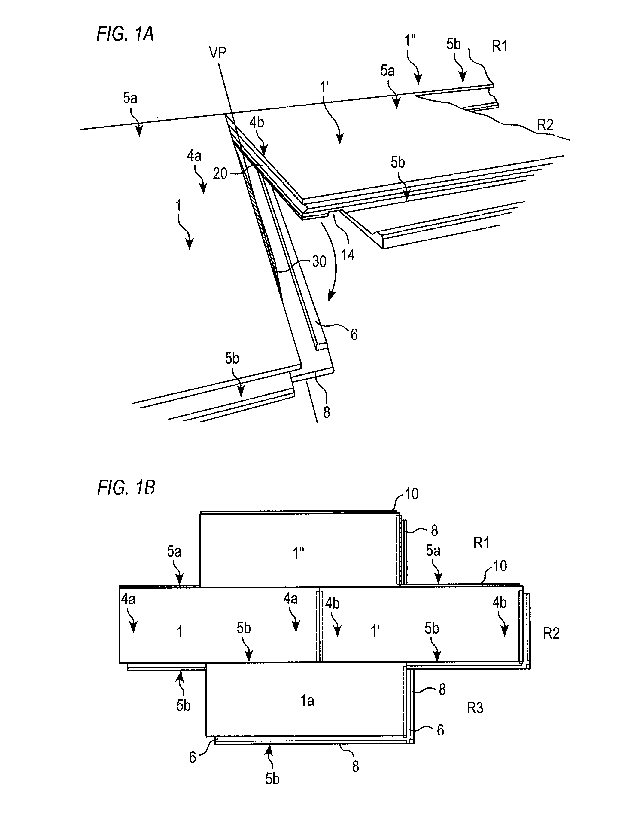
[0075]An embodiment of the invention is shown in FIG. 3A. A first floor panel 1, which comprises an upper first solid wood element 31 attached to a lower second wood element 32, is locked to an essentially identical second floor panel 1a. The first and the second floor panels 1, 1a are provided with a mechanical locking system which comprises, at a first edge 5b of the first floor panel 1, a locking strip 6 with a vertically protruding locking element 8. The locking element 8 cooperates with a locking groove 14 at a second edge 5a of the second panel 1a for horizontally locking of the first and the second panels 1, 1a, when a tension force is applied. The first element 31 is preferably attached to the second element 32 by gluing. The mechanical locking system may be formed in the first and the second elements 31, 32 by milling when the first and the second elements 31, 32 are attached to each other.

[0076]The mechanical locking system may further comprises a tongue groove 11 at the f...


PUM


Abstract

Building panels each comprise an upper first element of solid wood fixed to a lower second element of solid wood. The first and the lower second element are of different wood species. The building panels are provided with a mechanical locking system which comprises a locking strip at a first edge of a first building panel. The locking strip is provided with a locking element configured to cooperate with a locking groove at a second edge of a second building panel for horizontal locking of the first and the second building panels when a tension force is applied. The fibre direction of the first and the lower second elements is essentially along the first and the second edges. The lower second element has about the same or higher moisture shrinkage value than the first element. The locking strip comprises material of the lower second element.

Description

FIELD OF THE INVENTION[0001]The present invention relates to building panels, such as floor panels, a wall panel, a ceiling panel, a furniture component or the like. The building panels comprise an upper solid wood element and a lower solid wood element, and are provided with a mechanical locking system. The present invention also relates to a method for producing the building panel with the locking system and the upper and lower solid wood elements.TECHNICAL BACKGROUND[0002]Building panels of wood provided with a mechanical locking system are known and disclosed in, e.g., WO03 / 087498.[0003]Furthermore, building panels provided with a mechanical locking system comprising a displaceable and resilient tongue cooperating with a tongue groove for vertical locking are known and disclosed in, e.g., WO2006 / 043893. The tongue is a separate part and is made of, e.g., plastic, and positioned in an insertion groove at an edge of a panel. The tongue is pushed into the insertion groove during a ...

Claims


Application Information

Patent Timeline
Patent Type & Authority Applications(United States)
IPC IPC(8): E04F13/08
CPCE04F13/0894E04F15/02038E04F15/045E04F2201/0161E04F2201/045
Inventor PERVAN, DARKOBRANNSTROM, HANS
Owner VÄLINGE INNOVATION AB
Learn More