Inflatable Purge Dam Apparatus

a purge dam and apparatus technology, applied in the field ofinert gas welding, can solve the problems of not being able to use pipes with nps of 2 inches or 4 inches, and achieve the effect of being resistant to oxygen leakag

Active Publication Date: 2013-10-31
AQUASOL CORP LLC +1
View PDF3 Cites 34 Cited by
  • Summary
  • Abstract
  • Description
  • Claims
  • Application Information

AI Technical Summary

Benefits of technology

[0009]Embodiments of an improved inflatable purge dam apparatus are disclosed. In one aspect, the purge dam apparatus may be constructed may be constructed for use with pipes of different nominal pipe size (NPS). In another aspect, the purge dam apparatus may be constructed so as to be resistant to oxygen leakage around the outside of the purge bladders. If desired, both of the above features may be provided in a single device. Alternatively, the features could be separately provided in different devices.
[0010]Each embodiment has first and second inflatable purge bladders joined by a bridge conduit. The first purge bladder has a first interior gas-receiving chamber and defines a first port on one side thereof and a second port on another side thereof, with the first port and the second port being aligned proximate to a central longitudinal axis of the first purge bladder. The second purge bladder has a second interior gas-receiving chamber and defines a third port on one side thereof, with the third port being aligned proximate to a central longitudinal axis of the second purge bladder. The bridge conduit extends between the second port on the first purge bladder and the third port on the second purge bladder, and provides fluid communication between the first gas-receiving chamber and the second gas-receiving chamber. The bridge conduit has a pressure-sensitive gas discharge valve operable to release a purge gas into a weld zone formed between the first purge bladder and the second purge bladder when the purge bladders have been inflated with the purge gas to a predetermined sealing pressure that is effective to seal the weld zone.
[0011]In a first aspect of the disclosed subject matter, the inflatable purge dam apparatus is characterized by the first purge bladder and the second purge bladde

Problems solved by technology

Although such devices may work satisfactorily with several different pipe schedules within a single NPS (e.g., by relaxing the purge gas pressure to partially deflate the purge bladders as the pipe wall thickness increases and the inside diameter decreases), they are not intended to

Method used


Image

  • Inflatable Purge Dam Apparatus
  • Inflatable Purge Dam Apparatus
  • Inflatable Purge Dam Apparatus

Examples


Embodiment Construction

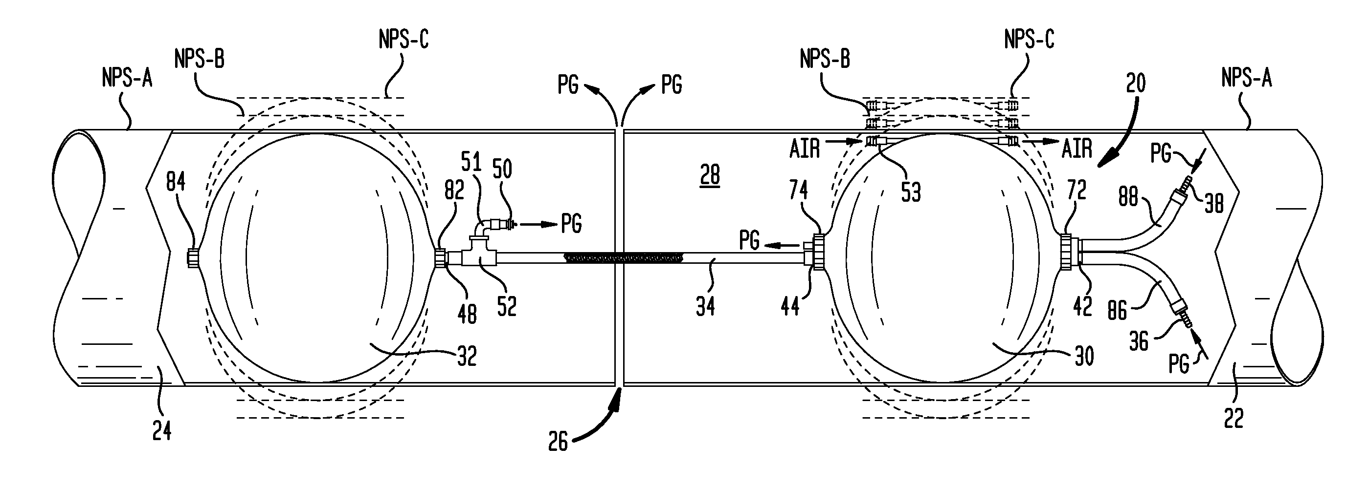
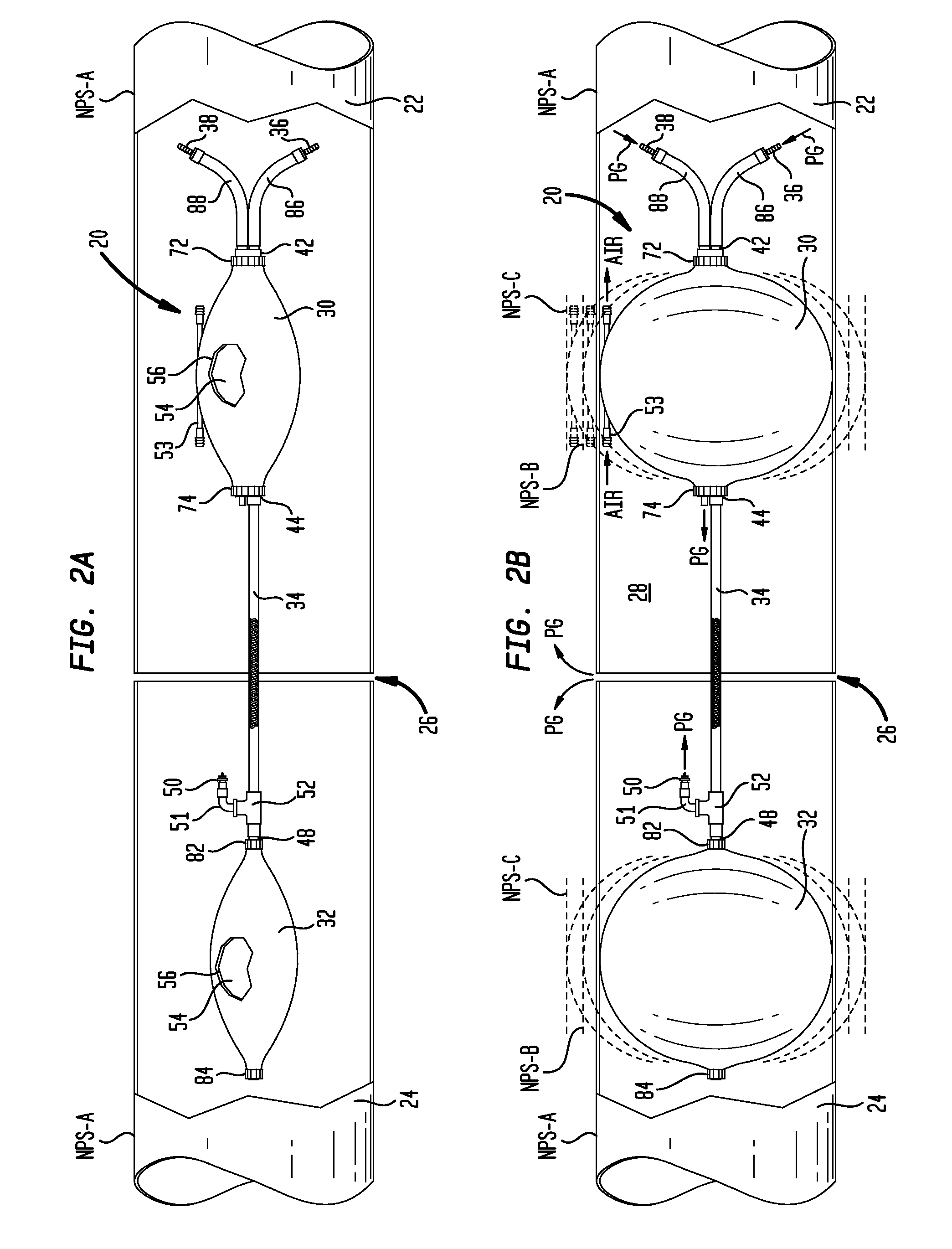
[0028]Turning now to the drawing figures, which are not necessarily to scale, like reference numbers are used to represent like elements in all of the several views. In FIGS. 2A and 2B, an example inflatable purge dam apparatus 20 is disposed inside a pair of pipes 22 and 24 that are to be butt-welded together at a welding root gap 26. The purge dam apparatus 20 has first and second inflatable purge bladders 30 and 32 that are joined together by an intermediate bridge conduit 34. FIG. 2A shows the purge dam apparatus 20 in a deflated condition following installation in the pipes 22 / 24 but prior to inflation of the purge bladders 30 / 32. FIG. 2B shows the purge dam apparatus 20 after the purge bladders 30 / 32 have been inflated with a purge gas PG. The enclosed space between the purge bladders 30 / 32 represents a weld zone 28 that has been purged of air by the purge gas following the introduction thereof through an optional inflation purge gas entry port 36 and possibly an optional auxi...


PUM


Abstract

An inflatable purge dam apparatus for use with pipes of different nominal pipe size (NPS) includes first and second inflatable purge bladders, and an intermediate bridge conduit. In a first aspect, the purge bladders each comprise an expandable inner purge gas retaining liner and a heat-resistant stretchable outer protective cover. The protective covers comprise a heat-resistant stretchable material that is constructed to undergo variable stretching to increase the size of the purge bladders as they are inflated with purge gas to a desired sealing pressure, thereby allowing the purge bladders to form an effective weld zone seal in pipes of different NPS. In a second aspect, an air vent conduit extends between first and second ports located proximate to a longitudinal centerline of the first purge bladder. The air vent conduit provides a vent pathway for venting air from the weld zone through the first purge bladder.

Description

BACKGROUND[0001]1. Field[0002]The present disclosure relates generally to inert gas welding. More particularly, the invention is directed to inflatable purge dams for retaining purge gas around a weld zone.[0003]2. Description of the Prior Art[0004]By way of background, inert gas welding is a species of arc welding in which the molten weld pool is shielded from atmospheric contamination and oxidation by bathing it with an inert gas, such as Argon, or a mixture of Helium and Argon. Popular examples of inert gas welding include TIG (Tungsten Inert Gas) welding and MIG (Metal Inert Gas) welding.[0005]When welding together pipes and other enclosed structures using inert gas welding, it is important to purge the interior of the pipe or structure in the vicinity of the weld zone to prevent corrosion and the formation of oxides on the interior side of the weld pool. Purge dams are conventionally used for this purpose. For example, when butt-welding the ends of two pipe sections to form a c...

Claims


Application Information

Patent Timeline
IPC IPC(8): F16L55/12
CPCB23K9/326F16L55/134
Inventor HACIKYAN, MICHAEL
Owner AQUASOL CORP LLC
Why Eureka
Try Eureka