
Antenna switching circuit and electronic device and antenna switching method thereof

Inactive Publication Date: 2013-10-31
GETAC TECH CORP
View PDF8 Cites 3 Cited by
  • Summary
  • Abstract
  • Description
  • Claims
  • Application Information

AI Technical Summary

Benefits of technology

The invention is a circuit and method for switching between an internal antenna and an external antenna in an electronic device. The circuit includes an external antenna connector and a controller with three terminals: RF, ground, and control. The controller detects the independent ground signal and connects the RF module or the internal antenna based on the signal. This allows for seamless switching between the two antennas without interrupting the communication. The technical effect is improved reliability and flexibility in wireless communication for electronic devices.

Problems solved by technology

However, reliability of the mechanical docking connector is gradually decreased after multiple plug / unplug operations.
Moreover, the mechanical docking connector results in high loss of transmission power of the RF signal.
Therefore, it is an important issue in the field to design a docking connector with low loss in transmission power and stable reliability.

Method used


Image

  • Antenna switching circuit and electronic device and antenna switching method thereof
  • Antenna switching circuit and electronic device and antenna switching method thereof
  • Antenna switching circuit and electronic device and antenna switching method thereof

Examples


first embodiment

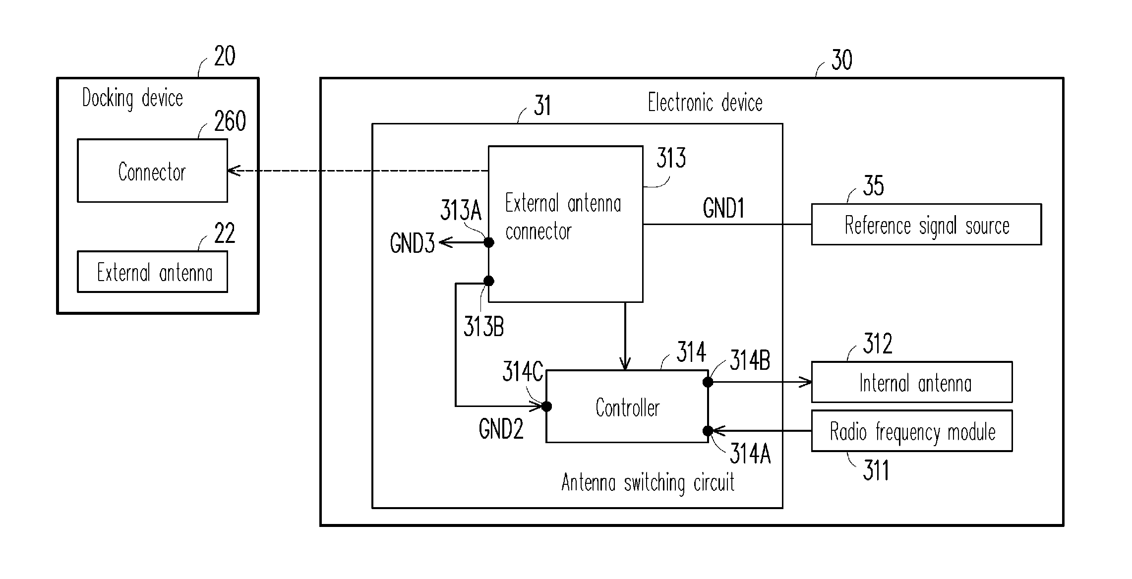
[0025]FIG. 4 is a block diagram of an electronic device according to the invention. Referring to FIG. 4, the electronic device 30 can be connected to a docking device 20 (or a docking system 20). The docking device20 includes a connector 260 and an external antenna 22.

[0026]The electronic device 30 includes an antenna switching circuit 31, a radio frequency (RF) module 311, an internal antenna 312 and a reference signal source 35.

[0027]The antenna switching circuit 31 includes an external antenna connector 313 and one controller or a plurality of controllers 314.

[0028]The internal antenna 312 is configured to transmit or receive RF signals. The RF module 311 is configured to generate or process the RF signals. The controller 314 is electrically connected to the external antenna connector 313.

[0029]The reference signal source 35 has a first ground signal GND1. In the present embodiment, the first ground signal GND1 is a common ground signal of the electronic device 30.

[0030]The exter...

second embodiment

[0031]The external antenna connector 313 may be a single connector (as shown in FIG. 4) or two connectors 315 and 316 (as shown in FIG. 5), where the first and the second connectors 315 and 316 are all external antenna connectors. When the electronic device 30 is connected to the docking device 20, the first and the second connectors 315 and 316 are connected to the connector 260 of the docking device 20. FIG. 5 is a block diagram of an electronic device according to the invention. When the external antenna connector 313 has two connectors (the first and the second connectors 315 and 316), the connection terminal 313A is configured on one of the two connectors (for example, on the first connector 315 of FIG. 5), and the independent ground terminal 313B is configured on the other of the two connectors (for example, on the second connector 316 of FIG. 5).

[0032]The controller 314 has a first RF terminal 314A, a second RF terminal 314B and at least one control terminal 314C. The first R...

fifth embodiment

[0050]FIG. 10 is a flowchart illustrating an antenna switching method according to the invention. Referring to FIG. 10 and FIG. 4, FIG. 8 or FIG. 9, the antenna switching method is adapted to the electronic device 30, 40 or 50, and includes following steps. An internal antenna and an RF module in the electronic device are electrically connected (step 610). An independent ground signal on an independent ground terminal of the electronic device is detected (step 620). When there is a change in the independent ground signal, the RF module is electrically connected to an external antenna (step 630).

[0051]After the step 630, the antenna switching method further includes a following step. When there is a change in the independent ground signal on the independent ground terminal, the internal antenna and the RF module are disconnected.

[0052]In summary, the invention provides the antenna switching circuit and the electronic device and the antenna switching method thereof. Using the electron...


PUM


Abstract

An antenna switching circuit and an electronic device and an antenna switching method thereof are provided. The antenna switching circuit is disposed in the electronic device including an internal antenna and a RF module, and includes an external antenna connector and a controller. The external antenna connector has an independent ground terminal for receiving an independent ground signal, and the external antenna connector is electrically connected to an external antenna. The controller has a first RF terminal, a second RF terminal and a control terminal, the first RF terminal is electrically connected to the RF module, the second RF terminal is electrically connected to the internal antenna, and the control terminal detects the independent ground signal. When the controller detects no change in the independent ground signal, the controller electrically connects the RF module to the internal antenna; otherwise, the controller electrically connects the RF module to the external antenna.

Description

BACKGROUND[0001]1. Field of the Invention[0002]The invention relates to an antenna switching circuit. Particularly, the invention relates to an antenna switching circuit connected to an external docking device and an electronic device and an antenna switching method thereof.[0003]2. Description of Related Art[0004]Vehicular telematics systems or industrial computers generally use a docking device to enhance convenience and performance of a computing device. Referring to FIG. 1, FIG. 1 is a schematic diagram of an electronic device connected to a docking device. The electronic device 10 includes a radio frequency (RF) module 11, an internal antenna 12 and a docking connector 13. The docking connector 13 is a mechanical docking connector which includes a first RF terminal 13A, a second RF terminal 13B and a third RF terminal 13C.[0005]When the electronic device 10 is not connected to a docking device (not shown in FIG. 1), the first RF terminal 13A is electrically connected to the rad...

Claims


Application Information

Patent Timeline
IPC IPC(8): H01Q3/24
CPCH01Q1/242H04B1/3877
Inventor LEE, YEN-CHINGCHIU, SHANG-MING
Owner GETAC TECH CORP
Features
  • Generate Ideas
  • Intellectual Property
  • Life Sciences
  • Materials
  • Tech Scout
  • Unparalleled Data Quality
  • Higher Quality Content
  • 60% Fewer Hallucinations
Learn More