Unidirectional microphone

a microphone and ribbon technology, applied in the direction of transducer details, electrical transducers, electrical apparatus, etc., can solve the problem that the output of a condenser microphone unit and an output from a ribbon microphone unit cannot be added together

a microphone and ribbon technology, applied in the direction of transducer details, electrical transducers, electrical apparatus, etc., can solve the problem that the output of a condenser microphone unit and an output from a ribbon microphone unit cannot be added together

US20130287223A1Inactive Publication Date: 2013-10-31AUDIO-TECHNICA

Image

  • Unidirectional microphone
  • Unidirectional microphone

Examples


Embodiment Construction

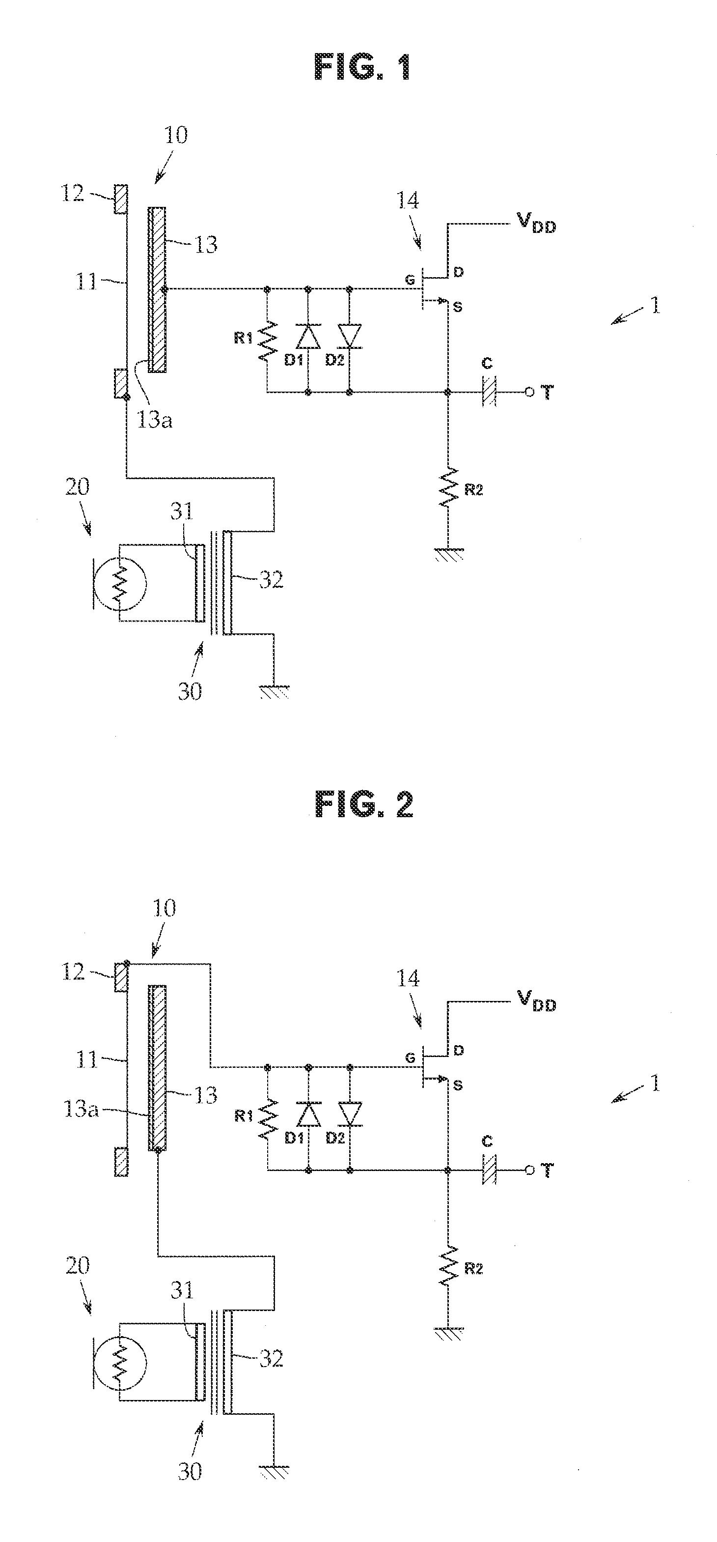
[0018]Embodiments of the present invention will now be described with reference to FIGS. 1 and 2, although the present invention is not limited to the embodiments.

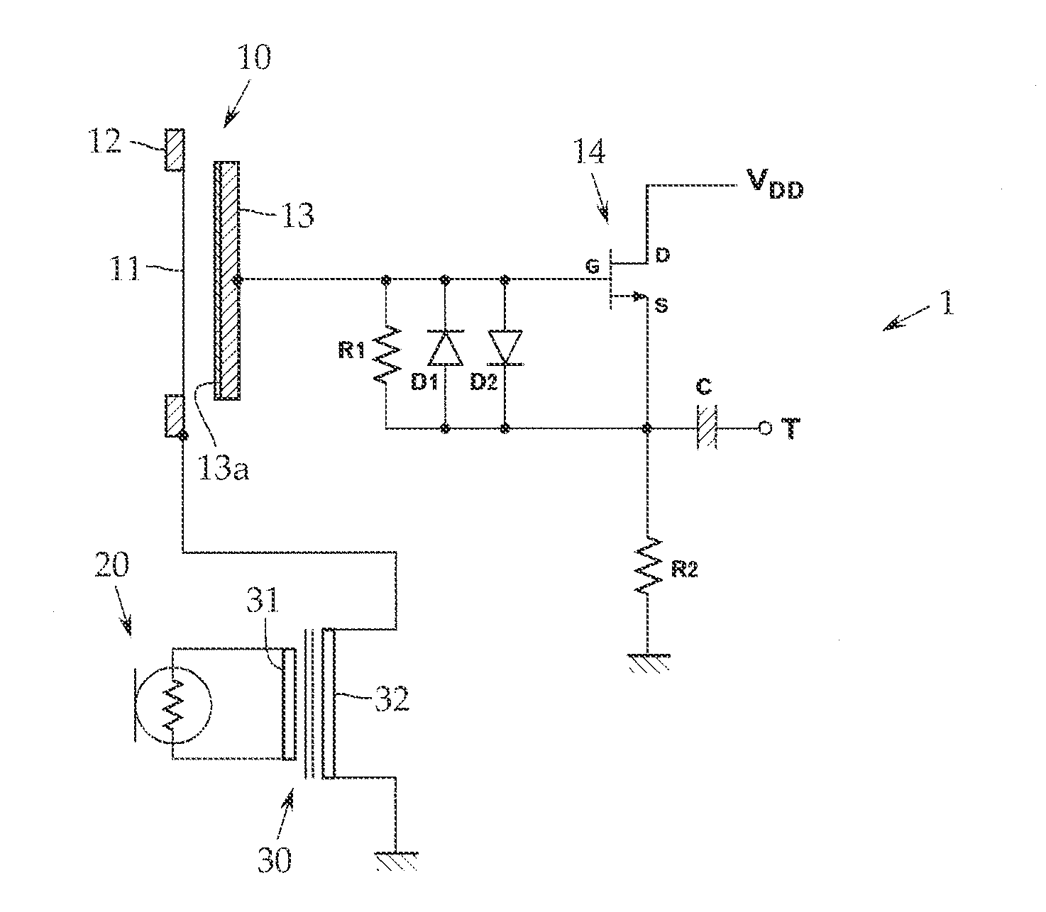
[0019]Referring first to FIG. 1, a unidirectional microphone 1 according to an embodiment includes an omnidirectional condenser microphone unit 10 that is a stiffness controlled unit suitable for being omnidirectional and a bi-directional ribbon microphone unit 20 that is a mass controlled unit suitable for being bi-directional.

[0020]The condenser microphone unit 10 is provided with an electroacoustic converter composed of a diaphragm 11, which is stretched over a diaphragm ring 12 with a predetermined tension, and a fixed pole 13. The diaphragm 11 and the fixed pole 13 are disposed to face each other with a spacer ring (not shown) interposed therebetween.

[0021]The diaphragm 11 may be a thin film of synthetic resin with a metallized film applied on one side. For example, the fixed pole 13 is an aluminum electrode plate and...


PUM


Abstract

The present invention provides a unidirectional microphone by adding an output from an omnidirectional condenser microphone unit and an output from a bi-directional ribbon microphone unit together. A condenser microphone unit 10 and a ribbon microphone unit 20 are connected in series via a step-up transformer 30, and the respective sound signals from the microphone units 10 and 20 are added together and are output from a source S of an FET 14.

Description

CROSS-REFERENCE TO RELATED APPLICATION[0001]The present application is based on, and claims priority from, Japanese Application Serial Number JP2012-100586, filed Apr. 26, 2012, the disclosure of which is hereby incorporated by reference herein in its entirety.TECHNICAL FIELD[0002]The present invention relates to a unidirectional microphone, and in particular to a unidirectional microphone composed of a combination of an omnidirectional microphone unit and a bi-directional microphone unit.BACKGROUND ART[0003]Outputs from an omnidirectional microphone unit and a bi-directional microphone unit can be added (combined) together to provide a unidirectional microphone (see “1-7-1 On the unidirectionality of combined microphones” co-written by Yoshinobu Yasuno, Michio Matsumoto, Hiroyuki Naono, and Mitsuhiro Katakura, Proceedings of the Meeting, The Acoustical Society of Japan, March 1982).[0004]Examples of combinations include a combination of a stiffness controlled omnidirectional conden...

Claims


Application Information

Patent Timeline
31 Oct 2013
Publication
US20130287223A1
IPC
H04R3/00
CPC
H04R3/00; H04R3/005
Inventors
AKINO, HIROSHI