Frame for speaker, speaker using same, and electronic apparatus and mobile device using speaker

a speaker and frame technology, applied in the field of loudspeaker frames, can solve problems such as the drawback of fair reliability to temperature change, and achieve the effect of improving the reliability to temperature chang

Active Publication Date: 2013-10-31
PANASONIC CORP
View PDF7 Cites 15 Cited by
  • Summary
  • Abstract
  • Description
  • Claims
  • Application Information

AI Technical Summary

Benefits of technology

[0010]This structure allows first and second stoppers which regulate it in the directions different from each other to couple the eyelet terminal securely with the connector hou

Problems solved by technology

Conventional loudspeaker 110 discussed above; however, h

Method used


Image

  • Frame for speaker, speaker using same, and electronic apparatus and mobile device using speaker
  • Frame for speaker, speaker using same, and electronic apparatus and mobile device using speaker
  • Frame for speaker, speaker using same, and electronic apparatus and mobile device using speaker

Examples


exemplary embodiment 1

[0022]A loudspeaker frame in accordance with Exemplary Embodiment 1 will be described below.

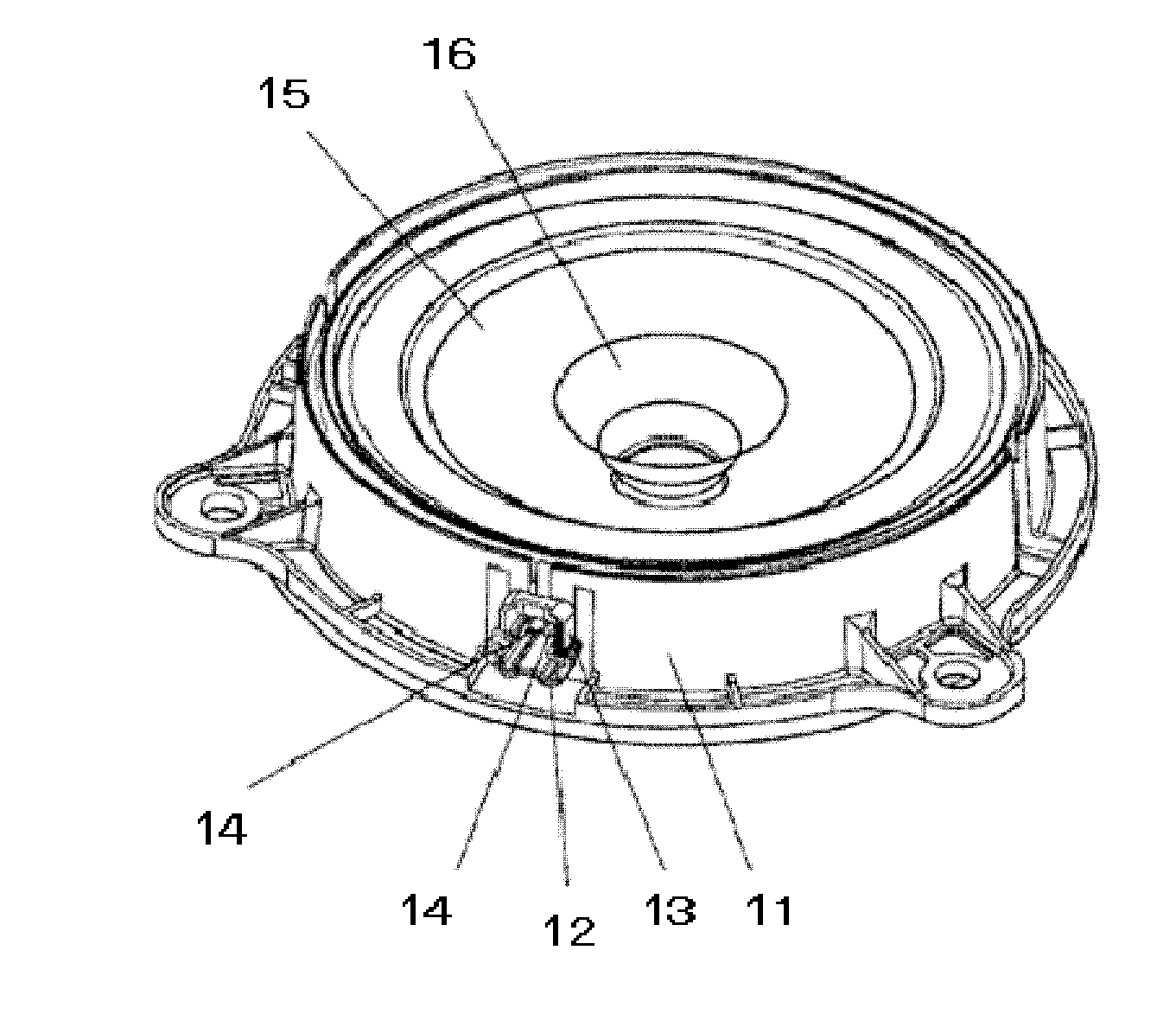
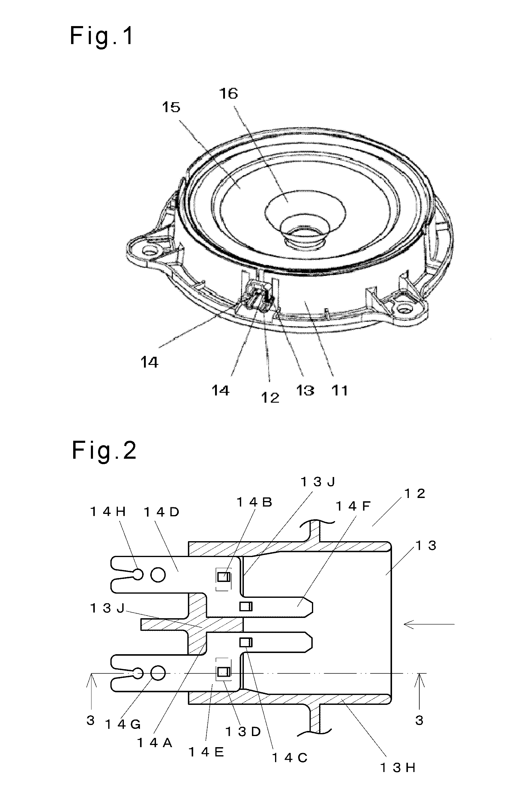
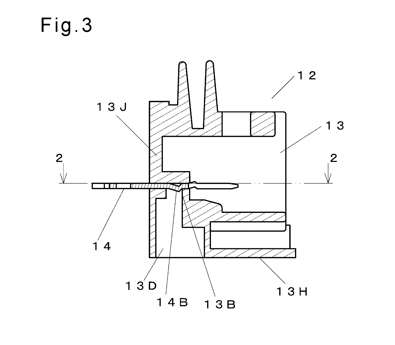
[0023]FIG. 1 is a perspective view of the loudspeaker frame in accordance with Embodiment 1 of the present invention. FIG. 2 is a sectional view of an enlarged essential part of a connector section of the loudspeaker frame in accordance with Embodiment 1. FIG. 3 is a sectional view of an enlarged essential part of the connector section cut along line 3-3 shown in FIG. 2.

[0024]FIG. 4A is a sectional view of an enlarged essential part of a connector housing of the loudspeaker frame in accordance with Embodiment 1. FIG. 4B is a front view of an eyelet terminal of the loudspeaker frame in accordance with Embodiment 1. In the following description, a plane direction refers to a direction viewed from a front (on a diaphragm side) of an assembled loudspeaker. In FIGS. 2 and 4, a lateral direction is an X-direction, and a vertical direction is a Y-direction. In FIG. 3, a vertical direction is a Z-dir...

exemplary embodiment 2

[0059]Exemplary Embodiment 2 will be demonstrated hereinafter. FIG. 7 is a sectional view of a loudspeaker in accordance with Embodiment 2 of the present invention. Magnetic circuit 24 used in the loudspeaker in accordance with Embodiment 2 is an inner magnet type magnetic circuit.

[0060]To be more specific, magnet 21 is sandwiched between upper plate 22 and yoke 23. Loudspeaker frame 11 in accordance with Embodiment 1 is coupled to yoke 23 of magnetic circuit 24.

[0061]The periphery of loudspeaker frame 11 is connected with an outer circumference of diaphragm 15. A first end of voice coil 28 is coupled to a center of diaphragm 15. A second end of voice coil 28 opposite to the first end is positioned in magnetic gap 25 of magnetic circuit 24. Sub-cone 16 is bonded to a front of voice coil 28.

[0062]Connector 12 is coupled with loudspeaker frame 11 as discussed in Embodiment 1. Eyelet terminal 14 is inserted into connector housing 13 to cause narrow section 14D to protrude from connecto...

exemplary embodiment 3

[0067]FIG. 8 is a schematic view of an electronic device in accordance with Exemplary Embodiment 3 of the present invention. According to Embodiment 3, audio mini-component system 44 is used as the typical electronic device. As shown in FIG. 8, a loudspeaker system is formed by incorporating loudspeakers 31 of the present invention into enclosure 41. This loudspeaker system includes amplifier 42 for amplifying an electric signal to be input to loudspeakers 31 and player 43 for supplying a source signal to be input into amplifier 42.

[0068]The above structure provides the electronic device that avoids the looseness between eyelet terminal 14 and connector housing 13 of loudspeaker 31, and the electronic device is resultantly free from abnormal sound caused by the looseness.

[0069]On top of that, since connector housing 13 is molded and simultaneously with frame 11 by injection molding the same resin, so that connector 12 is prevented from being taken off from frame 11 and the looseness...


PUM


Abstract

A connector housing made of resin includes a hole through which an eyelet terminal is inserted, a first wall for regulating a position of the eyelet terminal in an inserting direction of the eyelet terminal, and a second wall for regulating the position of the eyelet terminal in a direction opposite to the inserting direction of the eyelet terminal. The eyelet terminal includes a stopper contacts a wall surface and is provided at a place corresponding to the wall surface for regulating the position of the eyelet terminal in the inserting direction of the eyelet terminal, and a protrusion engaged with the second wall. The second wall is provided on a side wall surface of the hole. The above structure prevents the eyelet terminal from being taken off from the connector housing.

Description

TECHNICAL FIELD[0001]The present invention relates to a loudspeaker frame to be used in, e.g. vehicles, a loudspeaker using the loudspeaker frame, and an electronic device, such as a mobile device, using the loudspeaker.BACKGROUND ART[0002]FIG. 10 is a perspective view of a conventional loudspeaker.[0003]The loudspeaker includes frame 111 and connector 112 made of resin. Frame 111 and connector 112 are manufactured independently. Connector 112 includes connector housing 113 and two eyelet terminals 114 inserted into connector housing 113 to be and rigidly mounted to housing 113.[0004]Eyelet terminal 114 is inserted into connector to be rigidly mounted to connector housing 113 in the method below. First, eyelet terminal 114 is formed by punching with a metal die. At this moment, undulations having a sawtooth shape are formed in eyelet terminal 114. Then, eyelet terminal 114 is press-fitted into a hole provided in connector housing 113 so as to press-fit the undulations having the saw...

Claims


Application Information

Patent Timeline
IPC IPC(8): H04R1/00
CPCH04R1/00H04R1/06H04R9/06H04R2400/11H04R9/02
Inventor SASAKI, MATSUHIROHIRAGAKI, YASUYUKI
Owner PANASONIC CORP
Why Eureka
Try Eureka