Development device, process cartridge, and image forming apparatus

Active Publication Date: 2013-10-31
CANON KK
View PDF3 Cites 14 Cited by
  • Summary
  • Abstract
  • Description
  • Claims
  • Application Information

AI Technical Summary

Benefits of technology

[0014]The present invention is directed to providing a development device, a process cartridge, and an image forming apparatus which are simple in configuration and capable of stably forming a high quali

Problems solved by technology

However, in the method of supplying the developer discussed in Japanese Patent Application Laid-Open No. 2003-173083, if an image low in a printing ratio is continuously output, the developer is retained and coagulated between the

Method used


Image

  • Development device, process cartridge, and image forming apparatus
  • Development device, process cartridge, and image forming apparatus
  • Development device, process cartridge, and image forming apparatus

Examples


Example

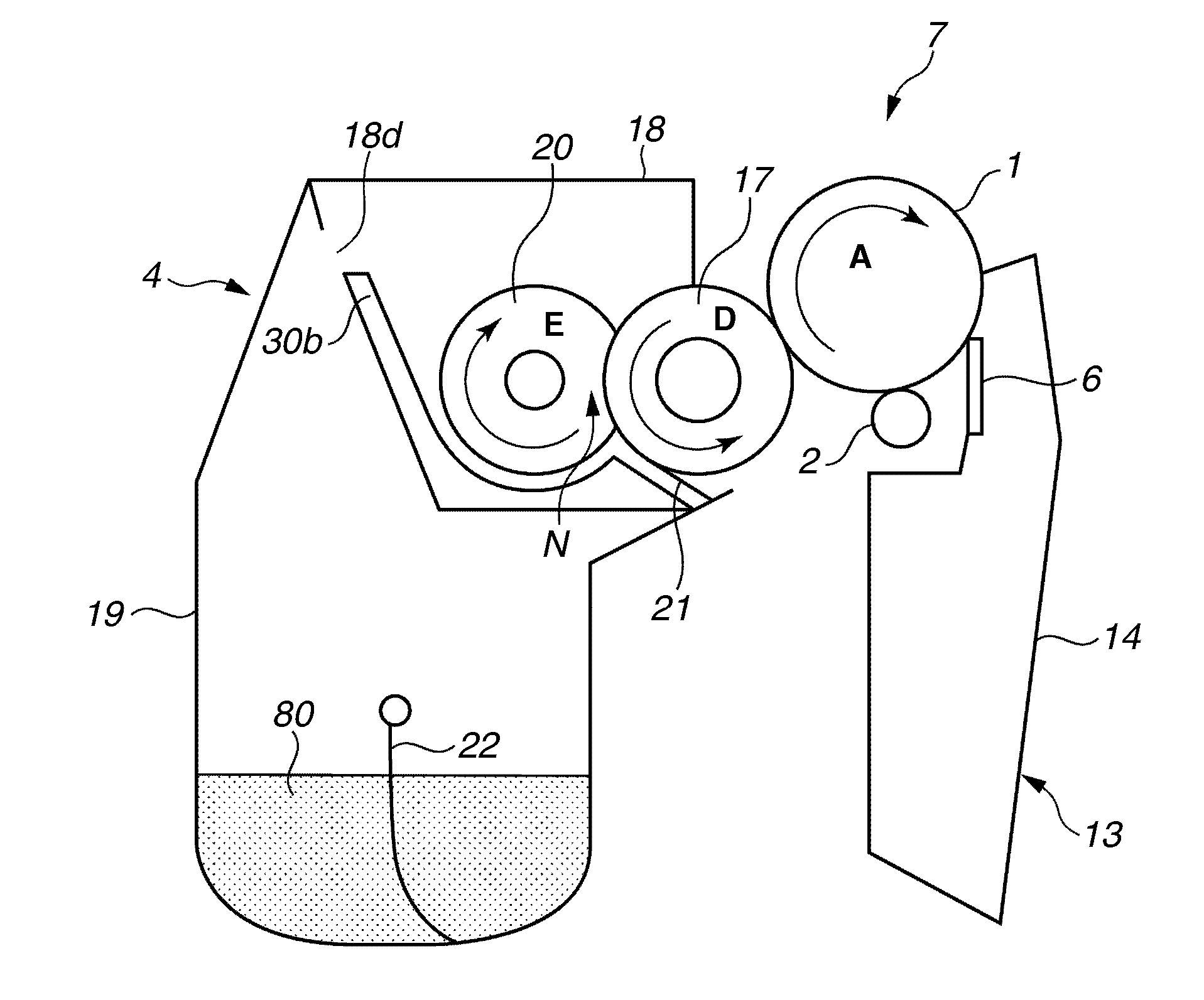
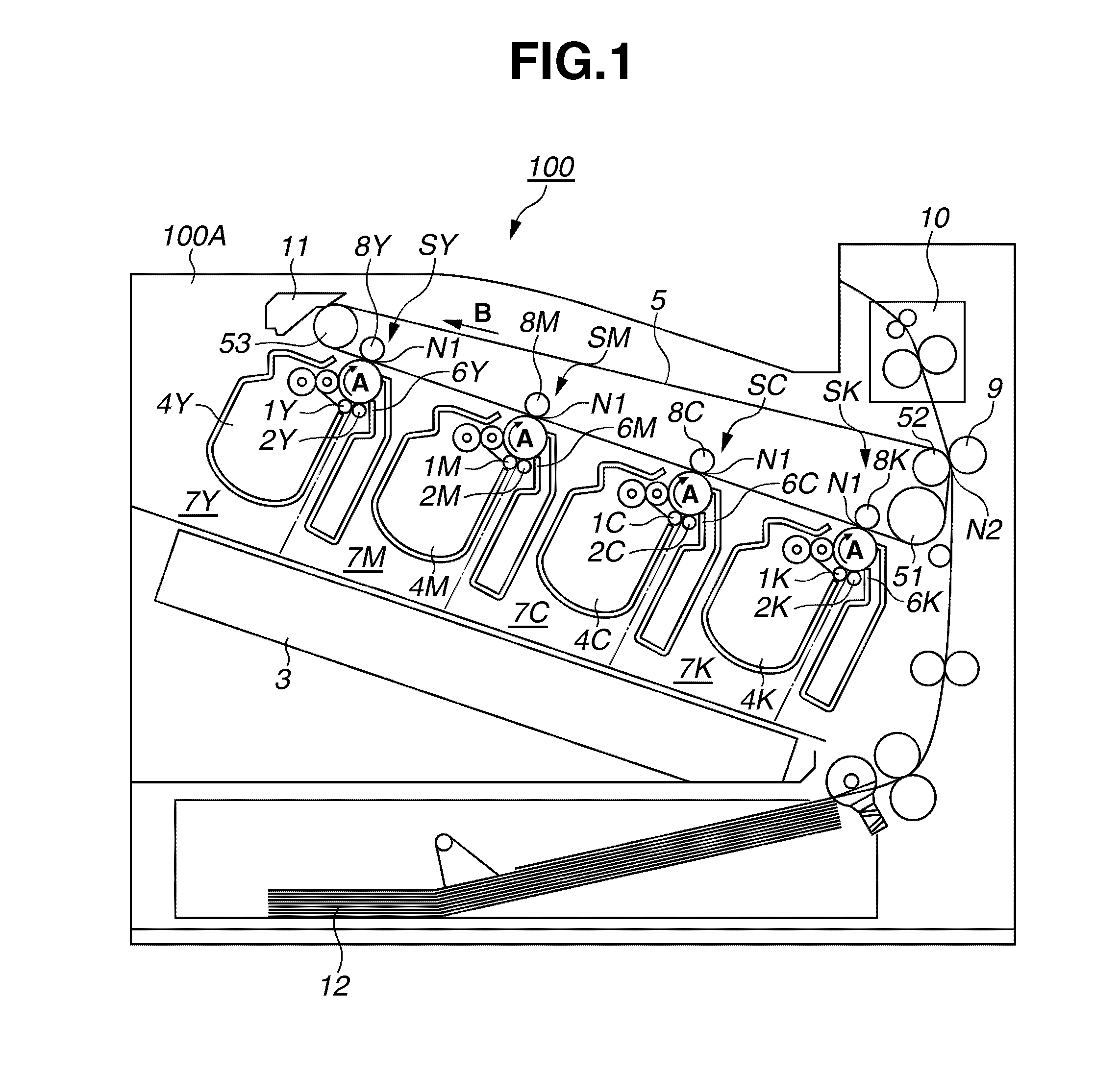
[0111]A second exemplary embodiment will be described below. A general configuration of an electrophotographic image forming apparatus (an image forming apparatus) according to the second exemplary embodiment is basically similar to that of the first exemplary embodiment (refer to FIG. 1). The process cartridge of the present exemplary embodiment is provided with configuration for optically detecting the remaining toner amount. Setting a desirable relationship between the direction of rotation of the supply roller and the configuration of the remaining toner amount enables improving the accuracy in the detection of remaining toner amount. A process cartridge 7 of the present exemplary embodiment is described below.

Process Cartridge

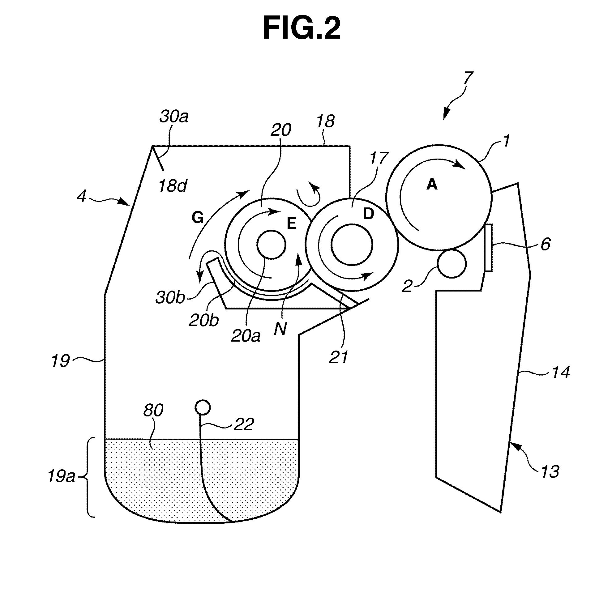
[0112]FIG. 6 is a schematic cross section (a principal section) of the process cartridge 7 according to the present exemplary embodiment, when viewed along the longitudinal direction of the photosensitive drum 1 (in the direction of a rotational axis line)...

Example

[0168]The third exemplary embodiment is described below with reference to FIGS. 13 and 14. The second exemplary embodiment has described the method of the remaining toner amount detection using the light-transmission members 40 in the toner containing chamber 19. The present exemplary embodiment discusses a method of the remaining toner amount detection in the second storage portion 18b.

[0169]The present exemplary embodiment has a configuration in which an antenna is provided as an electrode member used in a remaining toner amount detection device. The present exemplary embodiment is similar in other configurations to the second exemplary embodiment. As illustrated in FIG. 13, in the present exemplary embodiment, an antenna 50 for measuring electrostatic capacity is provided in an area where the toner is exactly accumulated in the second storage portion 18b. An alternating current (AC) bias with a frequency of 50 KHz and a peak-to-peak voltage (Vpp) of 200 V is used as a bias for t...


PUM


Abstract

In a development device in which a developer containing unit underlies a development chamber, a supplying member in the development chamber forms a nip portion with a developer carrier and the developer carrier and the supplying member rotate in the direction in which their respective surfaces move from an upper end to a lower end of the nip portion.

Description

BACKGROUND OF THE INVENTION[0001]1. Field of the Invention[0002]The present invention relates to an image forming apparatus for forming an image on a recording material using an electrophotographic system and, in particular, to a development device and a process cartridge applied to the image forming apparatus.[0003]2. Description of the Related Art[0004]In an image forming apparatus such as a printer using an electrophotographic image forming system (an electrophotographic process), an electrophotographic photosensitive member (hereinafter referred to as a “photosensitive member”) acting as an image carrier is uniformly charged, and the charged photosensitive member is selectively exposed to form an electrostatic image on the photosensitive member. The electrostatic image formed on the photosensitive member is visualized as a toner image by a toner as a developer. The toner image formed on the photosensitive member is transferred to a recording paper or a recording material such as...

Claims


Application Information

Patent Timeline
IPC IPC(8): G03G15/08
CPCG03G21/1817G03G15/0801G03G15/0865G03G21/1803G03G15/0806G03G15/0808
Inventor YOSHIDA, NOBUYOSHIMITSUI, YOSHIHIROHAYASHI, KODAIHIRATA, YUICHIROYAMAMOTO, SHINYA
Owner CANON KK
Why Eureka
Try Eureka