Shift control device and control method for continuously variable transmission

Inactive Publication Date: 2013-10-31
NISSAN MOTOR CO LTD
View PDF4 Cites 5 Cited by
  • Summary
  • Abstract
  • Description
  • Claims
  • Application Information

AI Technical Summary

Benefits of technology

The patent aims to solve a problem where the response delay in controlling the speed of a vehicle transmission occurs due to the elongation of the torque transmission member.

Problems solved by technology

As a result, it may not be possible to achieve the target speed ratio if the target speed ratio is set at the minimum speed ratio, for example, in an elongated state of the chain.
This causes a delay in the response of a speed ratio control when the target speed ratio is changed to a realizable high-side speed ratio later.

Method used


Image

  • Shift control device and control method for continuously variable transmission
  • Shift control device and control method for continuously variable transmission
  • Shift control device and control method for continuously variable transmission

Examples


second embodiment

[0076]Referring to FIGS. 9 and 10, this invention will be described.

first embodiment

[0077]Although the target speed ratio is set without considering the elongation of the V-chain 13 as in the conventional technology in the first embodiment, the target speed ratio Dip is determined in consideration of the elongation of the V-chain 13 in this embodiment.

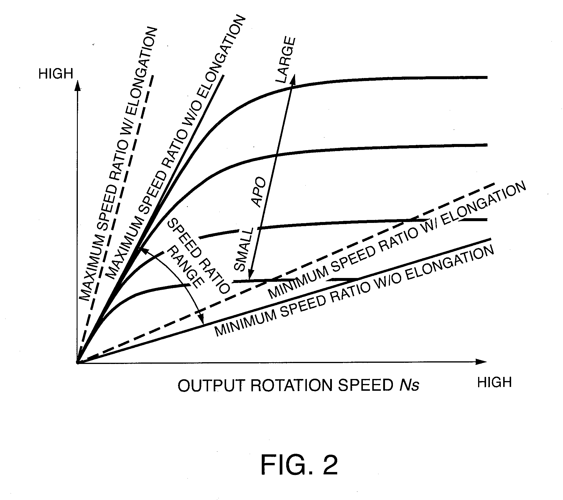
[0078]Specifically, the shift controller 22 determines the target speed ratio Dip by referring to a characteristic map shown in FIG. 9. FIG. 9 is similar to FIG. 2 and a minimum speed ratio with elongation, a minimum speed ratio without elongation, a minimum speed ratio with elongation and a minimum speed ratio without elongation in FIG. 2 are the same as in FIG. 2. The target speed ratio Dip is set between the maximum speed ratio without elongation and the minimum speed ratio without elongation in FIG. 2, whereas the target speed ratio is set between the maximum speed ratio with elongation and the minimum speed ratio without elongation in FIG. 9.

[0079]If the target speed ratio Dip is set based on the map of FIG. 9, a...

third embodiment

[0099]Referring to FIGS. 11 to 14 and 15A, 15B, this invention will be described.

[0100]In this embodiment, the target of the feedback control is a pulley thrust force and the elongation-affected shift condition is determined by a method different from those of the first and second embodiments.

[0101]The elongation-affected shift condition will be described in relation to the pulley thrust force. If a large slip occurs between the V-chain 13 and the primary pulley 11 or the secondary pulley 12 when the V-chain 13 transmits a torque between the primary pulley 11 and the secondary pulley 12, it is difficult to transmit the torque. Such a slip occurs due to a reduction in the thrust force of the primary pulley 11 or that of the secondary pulley 12. For normal torque transmission, a pulley thrust force not smaller than a slip limit thrust force needs to be applied to both the primary pulley 11 and the secondary pulley 12.

[0102]In the following description, a pulley thrust force applied to...


PUM


Abstract

A continuously variable transmission (4) shifts between a pair of pulleys (11, 12) via an endless torque transmission member (13) mounted on the pair of pulleys (11, 12). A controller (22) executes a feedback-control so that a real speed ratio between the pair of pulleys (11, 12) follows a target speed ratio (S6, S46). The controller (22) determines whether or not a elongation-affected shift condition, under which it is impossible for the real speed ratio to reach the target speed ratio depending on whether or not the endless torque transmission member (13) is elongated, holds (S2, S3, S12, S13), and limits a speed ratio feedback control when the elongation-affected shift condition holds (S4, S24, S34).

Description

FIELD OF THE INVENTION[0001]This invention relates to a shift control for a continuously variable transmission using an endless torque transmission member such as a chain.BACKGROUND OF THE INVENTION[0002]In a continuously variable transmission (CVT) using an endless torque transmission member such as a chain, the elongation of the endless torque transmission member affects a shift control. If the chain is elongated in a state where a winding radius on a primary pulley is fixed, a winding radius on a secondary pulley increases and a speed ratio changes to an increasing side, i.e. a so-called low side.[0003]JP08-327857A published in 1996 by the Japan Patent Office teaches to resolve a deviation between a target speed ratio and a real speed ratio by a speed ratio feedback control using a proportional-integral (PI) control. For example, even if the target speed ratio and the real speed ratio do not match due to the elongation of a chain, the real speed ratio eventually matches the targe...

Claims


Application Information

Patent Timeline
IPC IPC(8): F16H61/662
CPCF16H61/662F16H61/66259F16H9/125F16H2059/704
Inventor OKUDAIRA, KEITAKOGA, MASATO
Owner NISSAN MOTOR CO LTD
Why Eureka
Try Eureka