

Engine wear detection system
a wear detection and engine technology, applied in the field of engine instruments, can solve the problems of engine wear, insufficient to know only how many miles an automobile has traveled, and cannot provide a digital display of the number of revolutions,
- Summary
- Abstract
- Description
- Claims
- Application Information
AI Technical Summary
Benefits of technology
Problems solved by technology
Method used
Image

Examples
Embodiment Construction
)
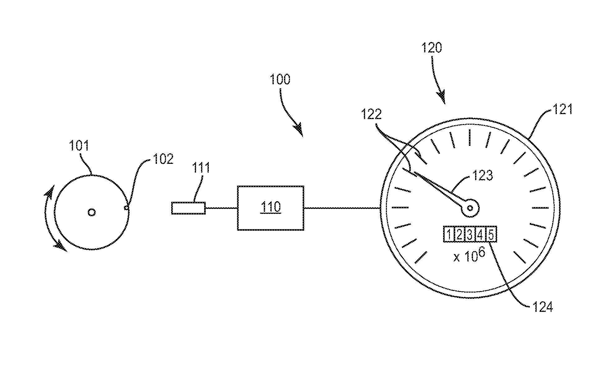
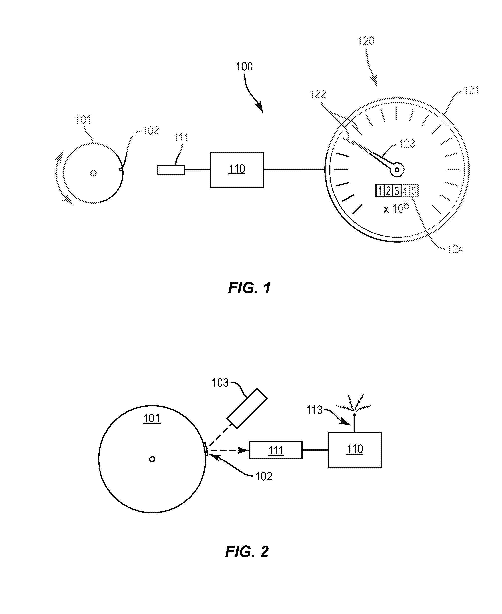
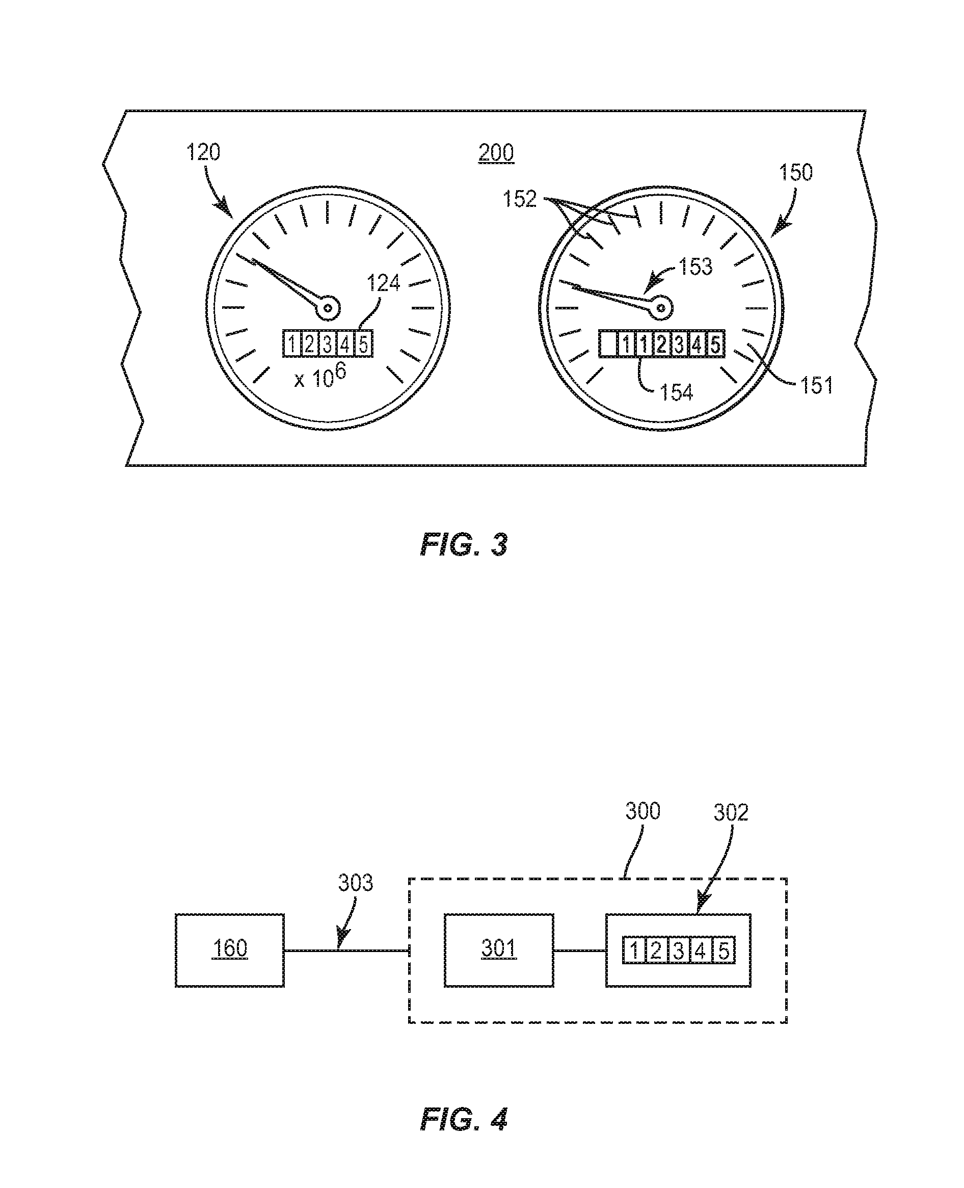
[0022]The present invention includes a cyclometric system associated with an engine for measuring the cumulative number of rotations of a rotary member of the engine (e.g., crankshaft, cam shaft, flywheel, etc.) and visually displaying the number in a cyclometer display. In an embodiment, the visual display of the number of rotations is in conjunction with a display of the rotation speed of the rotary member, for example, a combined cyclometer-tachometer display.
[0023]In another embodiment the invention includes a stand-alone cyclometer display in conjunction with the instrument panel, or dashboard, of a motor vehicle.
[0024]The present disclosure may be understood more readily by reference to the following detailed description of the disclosure taken in connection with the accompanying drawing figures, which form a part of this disclosure. It is to be understood that this disclosure is not limited to the specific devices, methods, conditions or parameters described and / or shown her...
PUM
 Abstract
Description
Claims
Application Information