Eureka AIR delivers breakthrough ideas for toughest innovation challenges, trusted by R&D personnel around the world.

Valve structure

Inactive Publication Date: 2013-11-07
NEWBUD INDAL CORP
View PDF6 Cites 2 Cited by
  • Summary
  • Abstract
  • Description
  • Claims
  • Application Information

AI Technical Summary

Benefits of technology

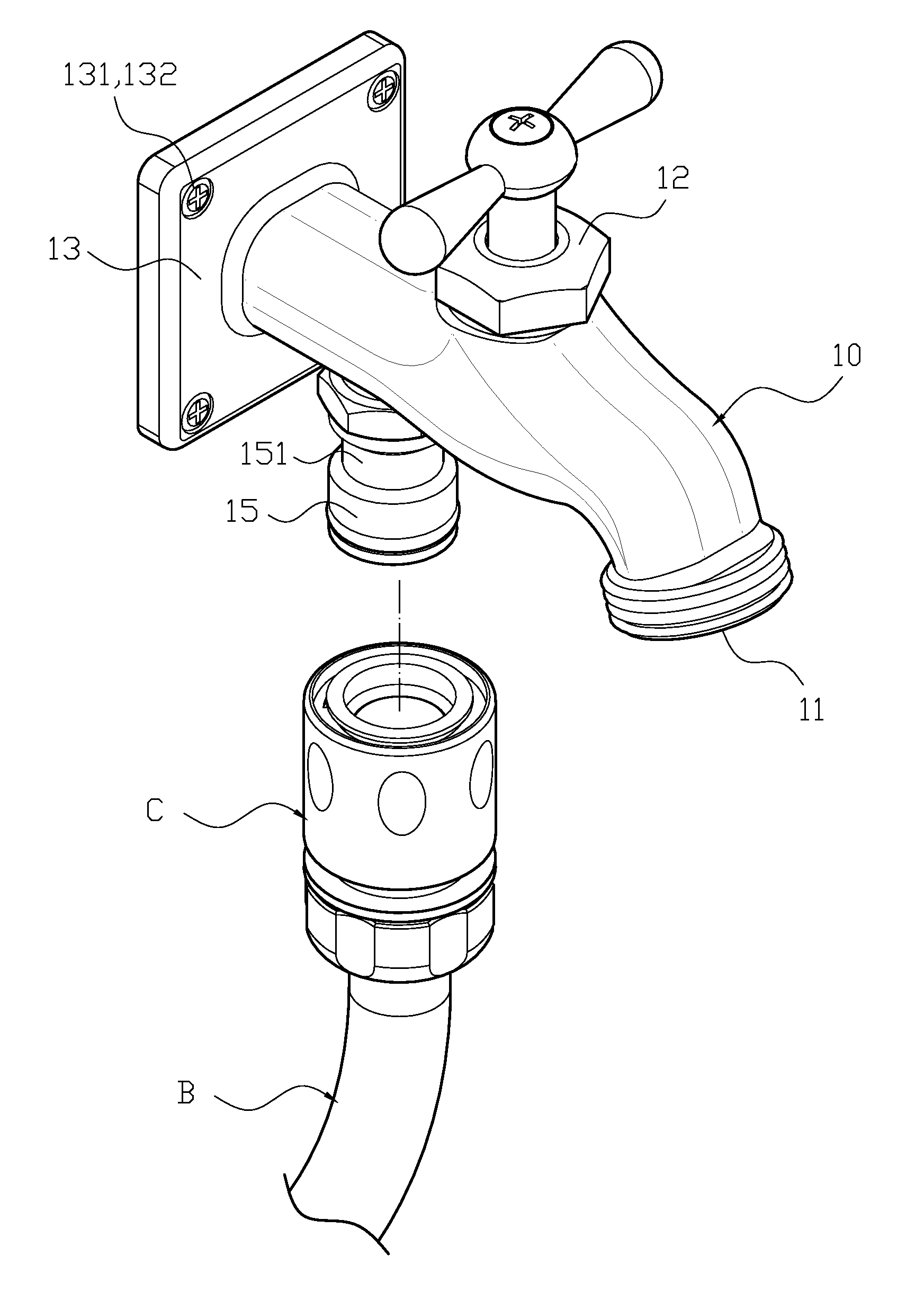
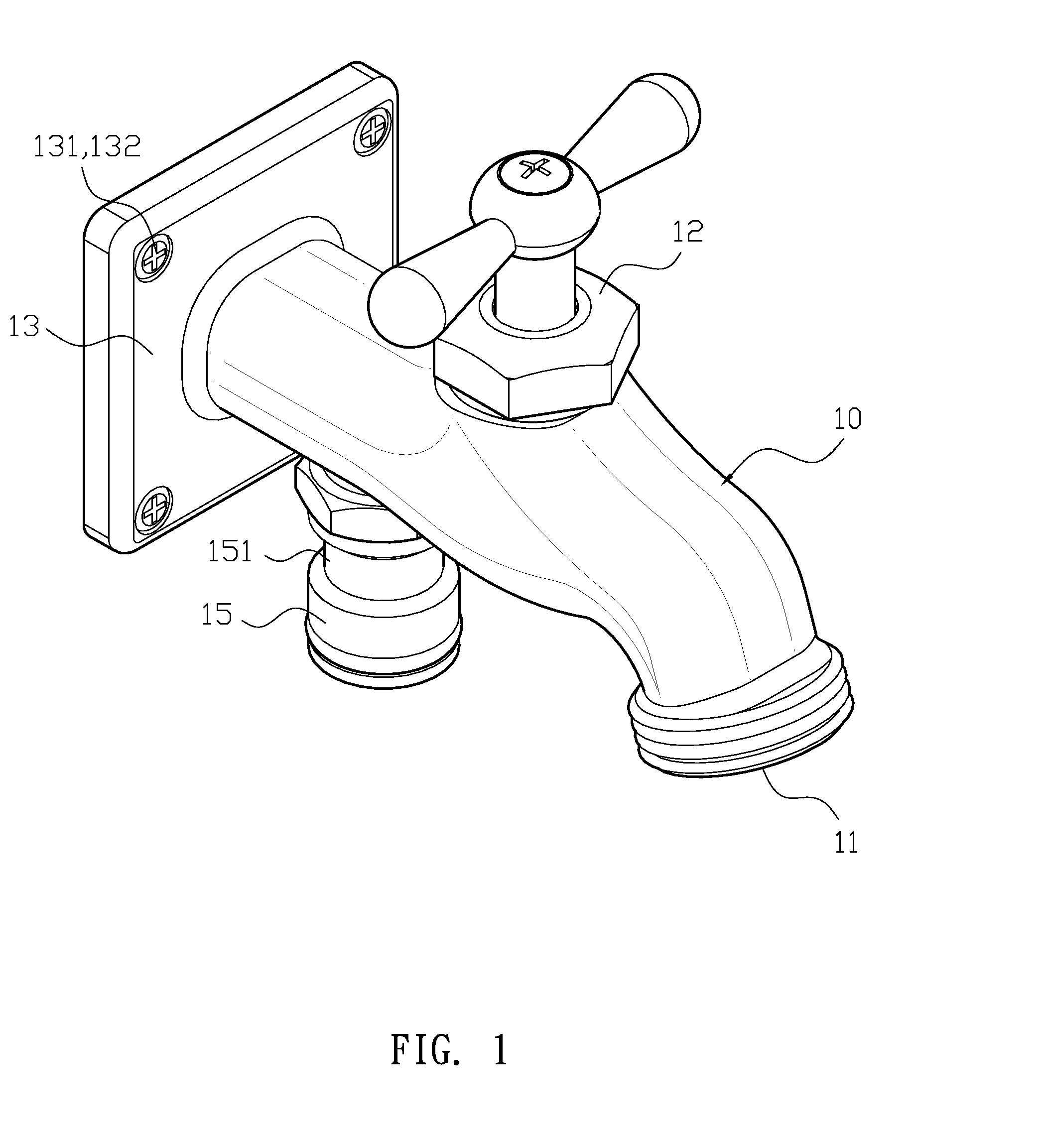
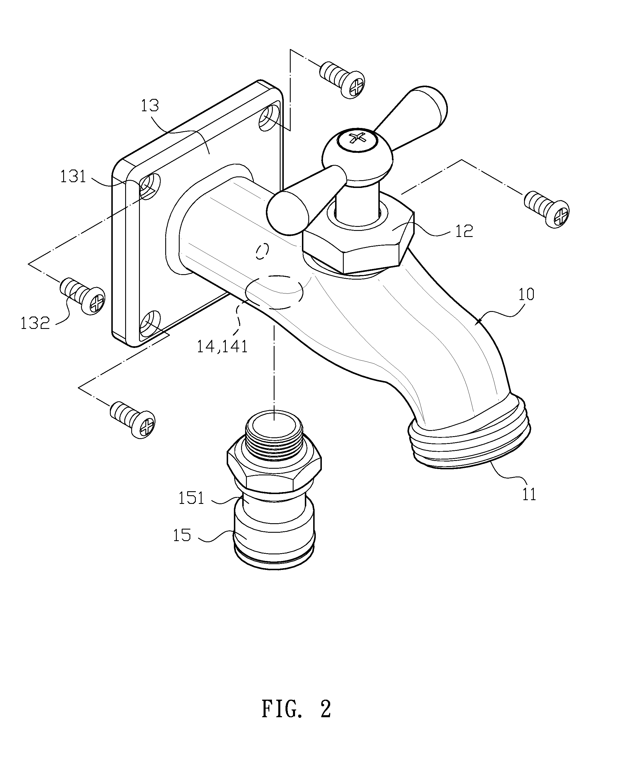
The present invention solves problems by using an existing pipeline system without the need for tedious and time-consuming pipeline burying. It allows for increased convenience and ease of installation by allowing the valve to be installed at any position on a fixed surface and connected to an existing water supplying end of the pipeline system through a connecting base and hose. This eliminates the need for extensive training or experience and allows for easy and secure assembly and adjustment of the valve position.

Problems solved by technology

However, the pipelines for water distribution has been arranged when the building was built, and if there is a need for a new water valve or trying to adjust a water outlet position of the water valve, the wall surface has to be destroyed to bury new pipelines or adjust pipeline positions, and then restored, which is tedious, time-consuming, and it is not appropriate for people without experience to conduct such work, but it may be expensive to hire experienced plumbers.

Method used


Image

  • Valve structure
  • Valve structure
  • Valve structure

Examples


Embodiment Construction

[0011]The detailed description set forth below is intended as a description of the presently exemplary device provided in accordance with aspects of the present invention and is not intended to represent the only forms in which the present invention may be prepared or utilized. It is to be understood, rather, that the same or equivalent functions and components may be accomplished by different embodiments that are also intended to be encompassed within the spirit and scope of the invention.

[0012]Unless defined otherwise, all technical and scientific terms used herein have the same meaning as commonly understood to one of ordinary skill in the art to which this invention belongs. Although any methods, devices and materials similar or equivalent to those described can be used in the practice or testing of the invention, the exemplary methods, devices and materials are now described.

[0013]All publications mentioned are incorporated by reference for the purpose of describing and disclos...


PUM

PropertyMeasurementUnit
Shapeaaaaaaaaaa

Abstract

A valve structure may include a tube body, a front end of which has a water outlet end, and a water control valve is located near the water outlet end to control the amount of output water. A connecting base extends backwards from the water control valve, and a water inlet hole is formed between the connecting base and the water control valve, and a connecting tube connects to the water inlet hole. According to the structure described above, the valve can be installed at any position of the fixed surface through the connecting base, and the connecting tube can be coupled with the hose to connect to an existing water supplying end of the pipeline system, the user does not have to conduct a tedious and time-consuming pipeline-burying process, so people without any experience can also assemble the valve and adjust the position thereof by themselves.

Description

FIELD OF THE INVENTION[0001]The present invention relates to a simple valve structure, and more particularly to a valve extending to a rear end forming a connecting base, so that the valve can be installed at any position of a fixed surface through the connecting base. A water inlet hole is disposed between the connecting base and a water control valve, and the water inlet hole is coupled with a tube connecting to a water source, such as a water supplying end with a pipeline system.BACKGROUND OF THE INVENTION[0002]When installing a conventional water valve, a pipeline has to be buried in advanced in the wall and provides a water outlet end protruding from the wall surface for the water supplying valve to connect. However, the pipelines for water distribution has been arranged when the building was built, and if there is a need for a new water valve or trying to adjust a water outlet position of the water valve, the wall surface has to be destroyed to bury new pipelines or adjust pip...

Claims


Application Information

Patent Timeline
IPC IPC(8): B22D41/16
CPCE03C1/0404Y10T137/9464
Inventor LIANG, TSANG-FU
Owner NEWBUD INDAL CORP
Why Eureka
Eureka Blog
Learn More