
Liquid discharge head and method for manufacturing the same

a liquid discharge head and liquid discharge technology, applied in the direction of electrical equipment, semiconductor devices, printing, etc., can solve the problems of failure of bonding, easy accumulation of heat,

Inactive Publication Date: 2013-11-07
CANON KK
View PDF4 Cites 2 Cited by
  • Summary
  • Abstract
  • Description
  • Claims
  • Application Information

AI Technical Summary

Benefits of technology

This configuration reduces wiring resistance and heat accumulation, enhancing the stability and reliability of the electrical connections in the liquid discharge head by managing heat and current flow effectively, thereby preventing bonding failures.

Problems solved by technology

However, the large width of the base of the inner lead causes an increase in inner lead's own reaction, creating a possibility that failures will occur during bonding.
Electric resistance then increases in a portion in which a width of the inner lead of the electric wiring member is small, causing heat to easily accumulate.

Method used


Image

  • Liquid discharge head and method for manufacturing the same
  • Liquid discharge head and method for manufacturing the same
  • Liquid discharge head and method for manufacturing the same

Examples


Embodiment Construction

[0020]Various exemplary embodiments, features, and aspects of the invention will be described in detail below with reference to the drawings.

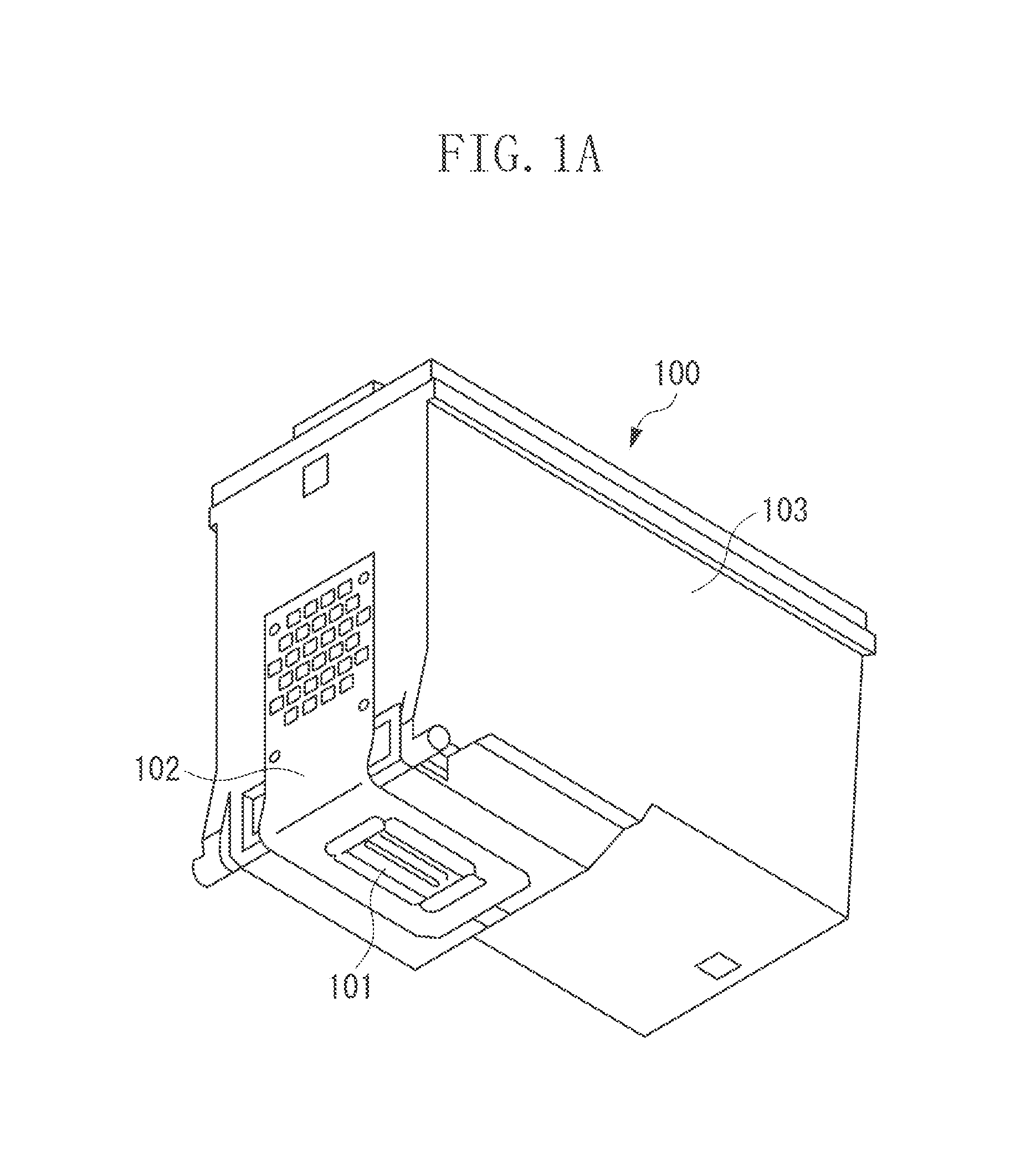
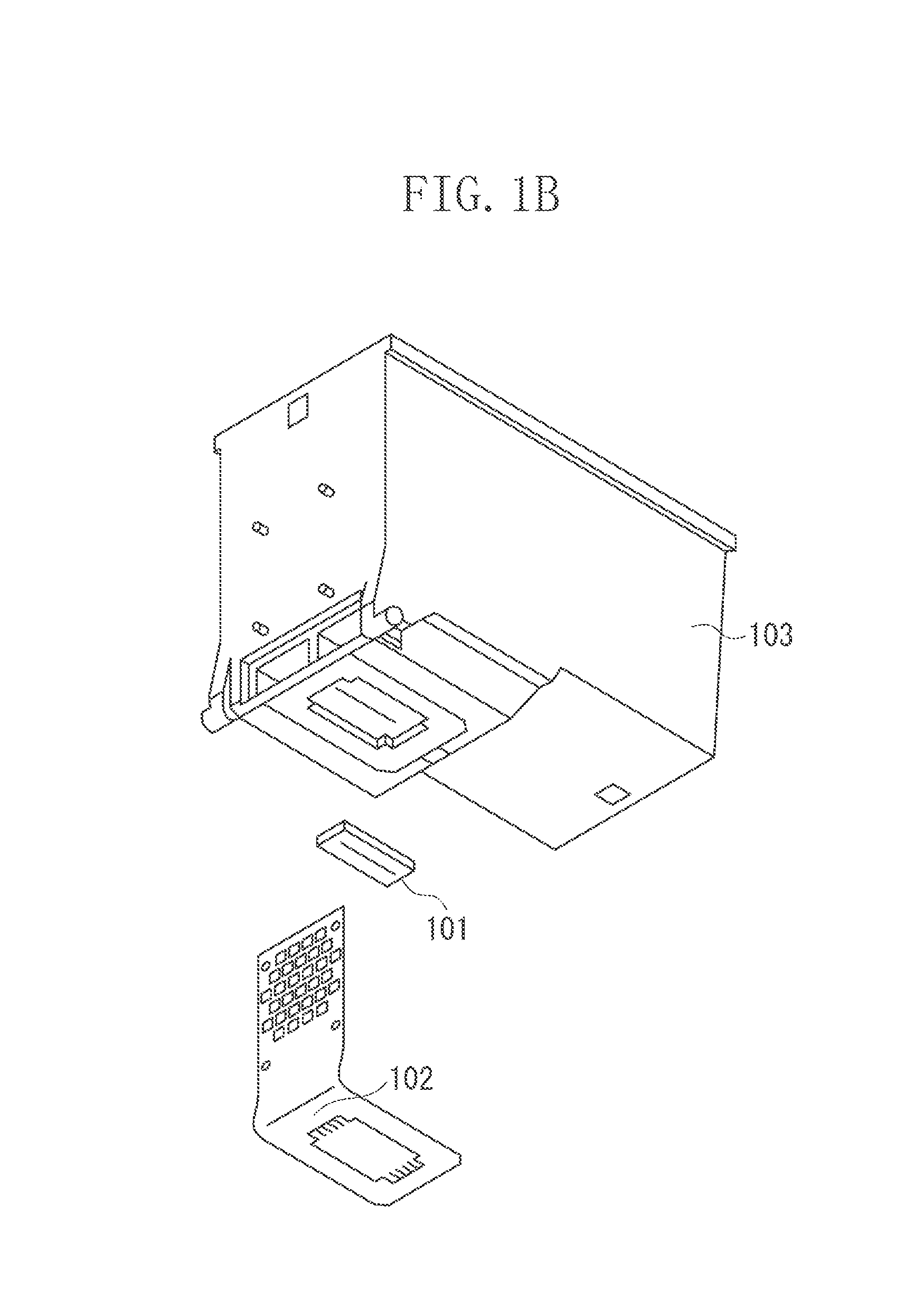
[0021]An exemplary embodiment of the present invention is described referring to the drawings. FIGS. 1A and 1B to FIGS. 5A and 5B illustrate a configuration of a liquid discharge head according to the exemplary embodiment of the present invention. FIG. 1A is a perspective view illustrating a liquid discharge cartridge 100 in which the liquid discharge head and an ink container 103 are integrally formed. FIG. 1B is an exploded perspective view illustrating a recording head. FIG. 2A is a plan view illustrating a front surface of a recording element substrate 101 included in the recording head. FIG. 2B is a plan view illustrating a rear surface of the recording element substrate 101. FIG. 3 is a plan view illustrating a surface of an electric wiring member 102 constituting a part of the recording head. FIG. 4 is a plan view illustrating a state wh...


PUM


Abstract

A liquid discharge head includes: a recording element substrate and a plurality of electric connection units; and an electric wiring member that includes a plurality of input terminals, a plurality wirings held between films and electrically connected to the plurality of input terminals, and a plurality of lead lines conducted to the plurality of wirings. In this case, the plurality of wirings include a power line for supplying power to the energy generation elements and a signal line for supplying a signal to the energy generation elements. Relationships of A>B and B<D are satisfied, in which A is a largest width of the signal line, B is a largest width of the lead line connected to the signal line, and D is a largest width of the lead line connected to the power line.

Description

CROSS REFERENCE TO RELATED APPLICATIONS[0001]This application is a Continuation of U.S. patent application Ser. No. 13 / 356,261 filed Jan. 23, 2012, which claims the benefit of Japanese Patent Application No. 2011-013276 filed Jan. 25, 2011, both of which are hereby incorporated by reference in their entirety.BACKGROUND OF THE INVENTION[0002]1. Field of the Invention[0003]The present invention relates to a liquid discharge head that discharges a liquid such as ink to perform a recording operation, and a method for manufacturing the same.[0004]2. Description of the Related Art[0005]The liquid discharge head includes an external signal input terminal electrically connected to a recording apparatus body side to receive, from a recording apparatus body, an electric signal or power used for driving an energy generation element that generates energy used for discharging a liquid. To connect the external signal input terminal to a recording element substrate that includes the energy generat...

Claims


Application Information

Patent Timeline
Patent Type & Authority Applications(United States)
IPC IPC(8): B41J2/01
CPCB41J2/01B41J2/1753B41J2/17553H01L2224/50Y10T29/49117
Inventor IINUMA, KEISUKEAMMA, HIROMASATODA, KYOSUKE
Owner CANON KK
Features
  • Generate Ideas
  • Intellectual Property
  • Life Sciences
  • Materials
  • Tech Scout
  • Unparalleled Data Quality
  • Higher Quality Content
  • 60% Fewer Hallucinations
Learn More