Method for placing at least one duct/communication cable below a road surface in an area

a technology of ducts and communication cables, applied in metal sawing accessories, instruments, roads, etc., can solve the problems of increasing the cost of connecting, affecting the expansion of fibre optic networks in residential areas, and high excavation and restoration costs of road layers, so as to reduce the cost of fibre installation

Active Publication Date: 2013-11-07
GUSTAVSSON CONNY MR +2
View PDF16 Cites 42 Cited by
  • Summary
  • Abstract
  • Description
  • Claims
  • Application Information

AI Technical Summary

Benefits of technology

[0005]An object of the present invention is to provide a method which fully or in part solves the problems of prior art solutions. Another object of the present invention is to provide a method for placing at least one duct / cable (e.g. communication cable) below a road surface in an area in a way that reduces the cost for fibre installation compared to prior art methods. Yet another object of the present invention is to provide an alternative method for placing at least one duct / communication cable below a road surface in an area.
[0011]With a method according to the present invention ducts / communication cables are placed at safe depth. This means that the fibre optic network will be safe if the road surface is removed and / or replaced. Further, the invention provides a method with minimum damage made to roads when placing ducts / cables which reduces the cost for restoration of the same.

Problems solved by technology

The expansion of fibre optic networks for communication in residential areas is often hampered by the high cost of excavation and restoration of the road layer, such as asphalt or concrete.
A typical residential connection may cost approximately EUR 3 000 plus VAT, and hence many homeowners are reluctant to make such an investment.
This in turn means that the connection rate for houses is low when a residential area is built, which further increases the cost of connecting.
An alternative, to provide house connections through green open spaces at the back of houses is in most cases not possible.
There is also the question of flowerbeds, bushes and trees, which can be costly to replace / restored.
Finally, it would probably be an enormous task to arrange permission from all the homeowners affected if this method should be employed.

Method used


Image

  • Method for placing at least one duct/communication cable below a road surface in an area
  • Method for placing at least one duct/communication cable below a road surface in an area
  • Method for placing at least one duct/communication cable below a road surface in an area

Examples


Embodiment Construction

[0025]To achieve the above mentioned objects a method for placing at least one duct / communication cable below a road surface in an area is provided by the inventors.

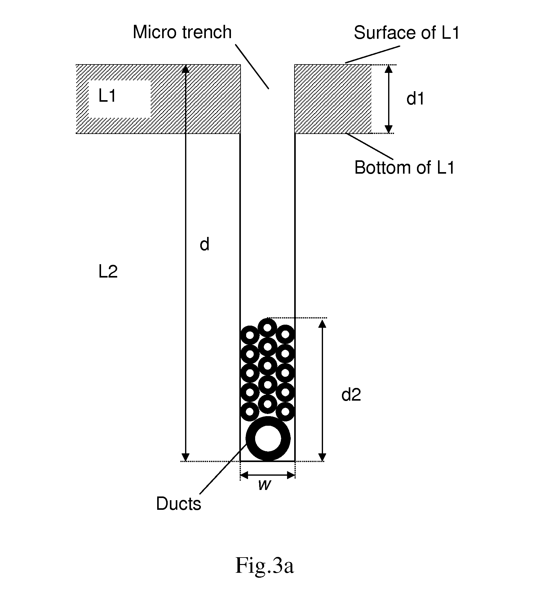
[0026]The area comprises a first layer L1 and a second layer L2. The first layer L1 is a road layer, such as asphalt or concrete, and the second layer L2 is a bearing layer for the first layer L1 and is located below the first layer L1.

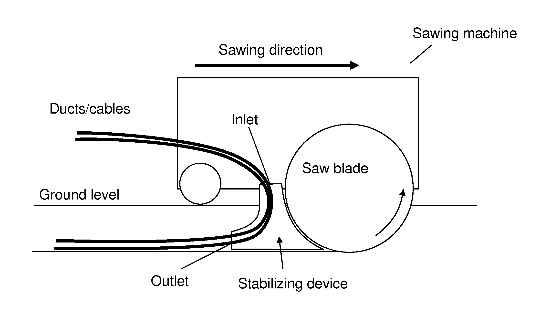
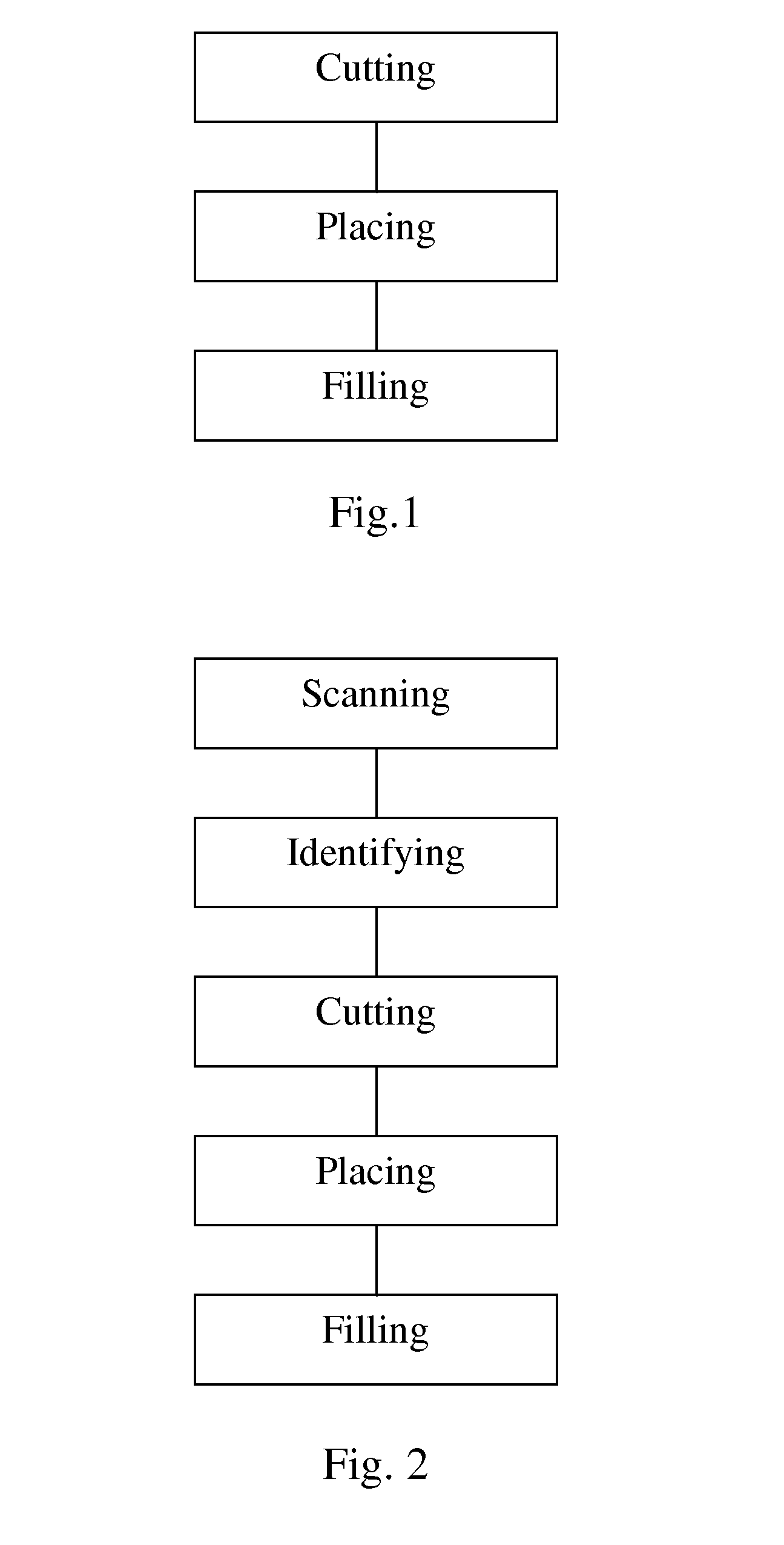
[0027]With reference to FIG. 1, which shows a flow chart of a method according to the present invention, the method for placing at least one duct / communication cable below a road surface in the area comprises the steps of:[0028]cutting a micro trench in the area through the first layer L1 into the second layer L2;[0029]placing at least one duct / communication cable in the micro trench so that the at least one duct / communication cable is placed below the first layer L1; and[0030]filling the micro trench so as to restore the road surface.

[0031]FIGS. 3a and 3b schematically shows a cross secti...


PUM

PropertyMeasurementUnit
widthaaaaaaaaaa
widthaaaaaaaaaa
widthaaaaaaaaaa

Abstract

The present invention relates to a method for placing at least one duct / communication cable below a road surface in an area, said area comprising a first layer (L1 and a second layer (L2), said first layer (L1) being a road layer, such as asphalt or concrete, and said second layer (L2) being a bearing layer for said first layer (L1) and being located below said first layer (L1), said method comprising the steps of: cutting a micro trench in said area through said first layer (L1) into said second layer (L2); placing at least one duct / communication cable in said micro trench so that said at least one duct / communication cable is placed below said first layer (L1); and filling said micro trench so as to restore said road surface.

Description

TECHNICAL FIELD [0001]The present invention relates to method for placing at least one duct / communication cable below a road surface in an area. More specifically, the invention relates to a method according to claim 1.BACKGROUND OF THE INVENTION[0002]The expansion of fibre optic networks for communication in residential areas is often hampered by the high cost of excavation and restoration of the road layer, such as asphalt or concrete. A typical residential connection may cost approximately EUR 3 000 plus VAT, and hence many homeowners are reluctant to make such an investment. This in turn means that the connection rate for houses is low when a residential area is built, which further increases the cost of connecting. The reason for this is that the cost for the backbone is more or less independent of the connection rate, and a low connection rate means that fewer houses will have to bear the total cost for the backbone.[0003]An alternative, to provide house connections through gr...

Claims


Application Information

Patent Timeline
Patent Type & Authority Applications(United States)
IPC IPC(8): F16L1/032H02G1/06G02B6/50E02F5/10
CPCF16L1/032E02F5/10H02G1/06G02B6/504E02F5/101E02F5/12E02F9/245H02G9/06E02F5/08B23D61/025B28D1/045B28D7/005Y10T83/849Y10T83/9457Y10T83/852Y10T83/175Y10T83/866Y10T83/929E02D27/46B23D59/001B23D59/008G05D3/10B23D61/18E02F5/00F16L1/028E01C23/09E02F5/18
Inventor GUSTAVSSON, CONNYHULTMAN, HASSE
Owner GUSTAVSSON CONNY MR
Why Eureka
Try Eureka