Battery housing structure

a battery and housing technology, applied in the field of battery housing structures, can solve the problems of affecting the uniformity of temperature the liable rise of the temperature around the electrode terminal, and the inability to discharge current in the electrode terminal, so as to achieve efficient heat radiation, enhance the uniformity of temperature, and reduce the heat resistance at the interface between the first wall and the plate.

Inactive Publication Date: 2013-11-07
NGK INSULATORS LTD
View PDF11 Cites 12 Cited by
  • Summary
  • Abstract
  • Description
  • Claims
  • Application Information

AI Technical Summary

Benefits of technology

[0019]According to the present invention, the heat is allowed to radiate from the inside of the container to the space, to which the heat is allowed to radiate, via mainly the first wall and the first portion. Moreover, the space, in which the battery is housed, and the space, to which the heat is allowed to radiate, are apart from each other via the second portion. Consequently, the heat hardly flows from the space, to which the heat is allowed to radiate, to the space, in which the battery is housed, so that temperature around the electrode terminal hardly rises.
[0020]According to the fourth aspect of the present invention, the second portion is deformed whereas the first portion is pressed against the first wall, and heat resistance at an interface between the first wall and the plate is reduced, thus efficiently allowing the heat to radiate.
[0021]According to the fifth aspect of the present invention, the heat is allowed to radiate from the inside of the container to the space, to which the heat is allowed to radiate, via mainly the first wall, the thermal conducting medium, and the first portion. The space, in which the battery is housed, and the space, to which the heat is allowed to radiate, are separated from each other via...

Problems solved by technology

In this case, when heat is allowed to radiate from the inside of the container to the outside thereof, temperature around an electrode terminal is liable to rise.
If the temp...

Method used


Image

  • Battery housing structure
  • Battery housing structure
  • Battery housing structure

Examples


first embodiment

[0034](Outline of Battery Housing Structure)

[0035]A first embodiment relates a battery housing structure in a power storage device. The battery housing structure in the first embodiment is desirably combined with a constituent such as a bidirectional converter, a transformer, or a control circuit, to thus configure a power storage device. The power storage device is desirably connected to an electric system so as to adjustably supply and demand electric power. The battery housing structure in the first embodiment may be combined with other constituents, or may configure a device other than the power storage device.

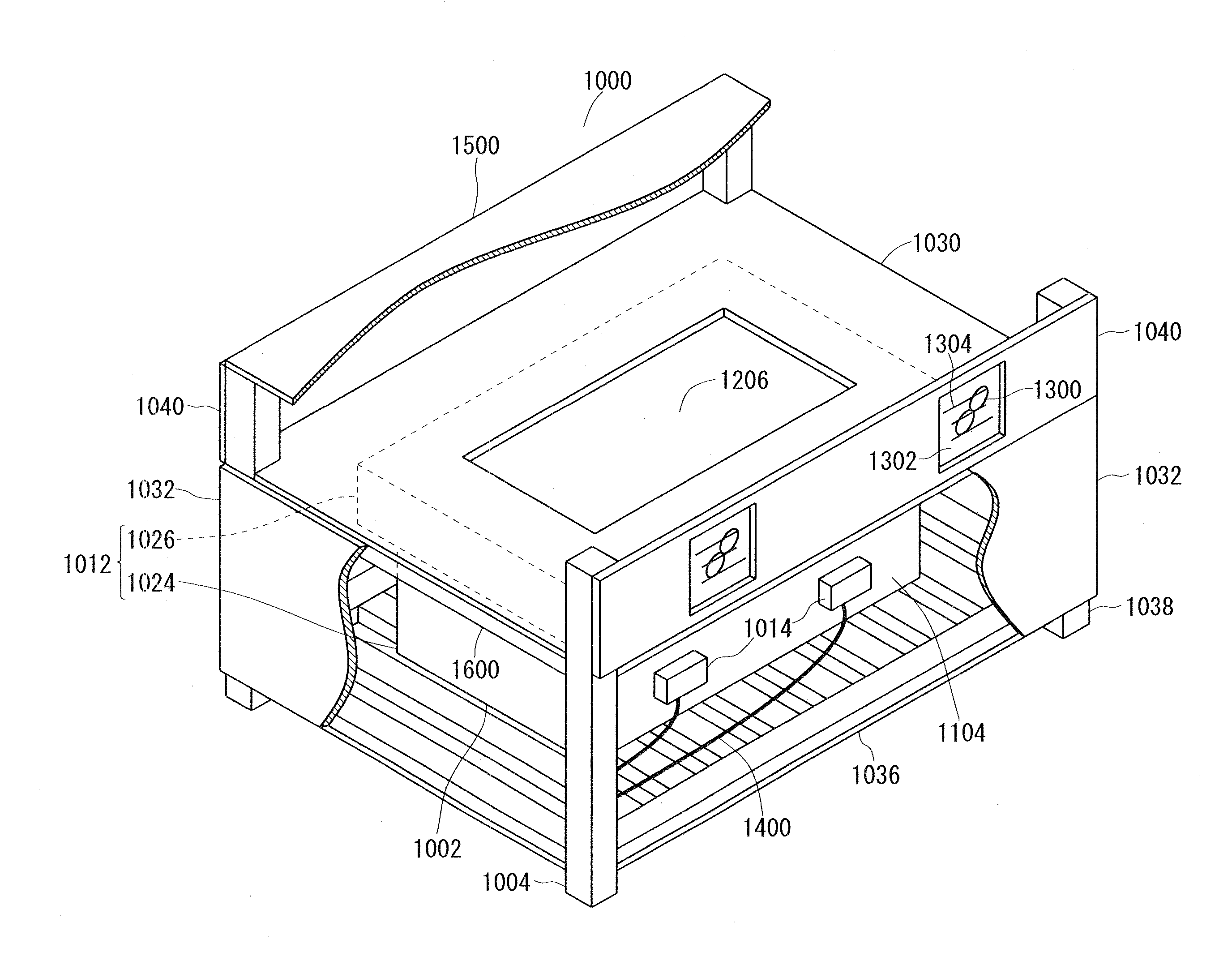
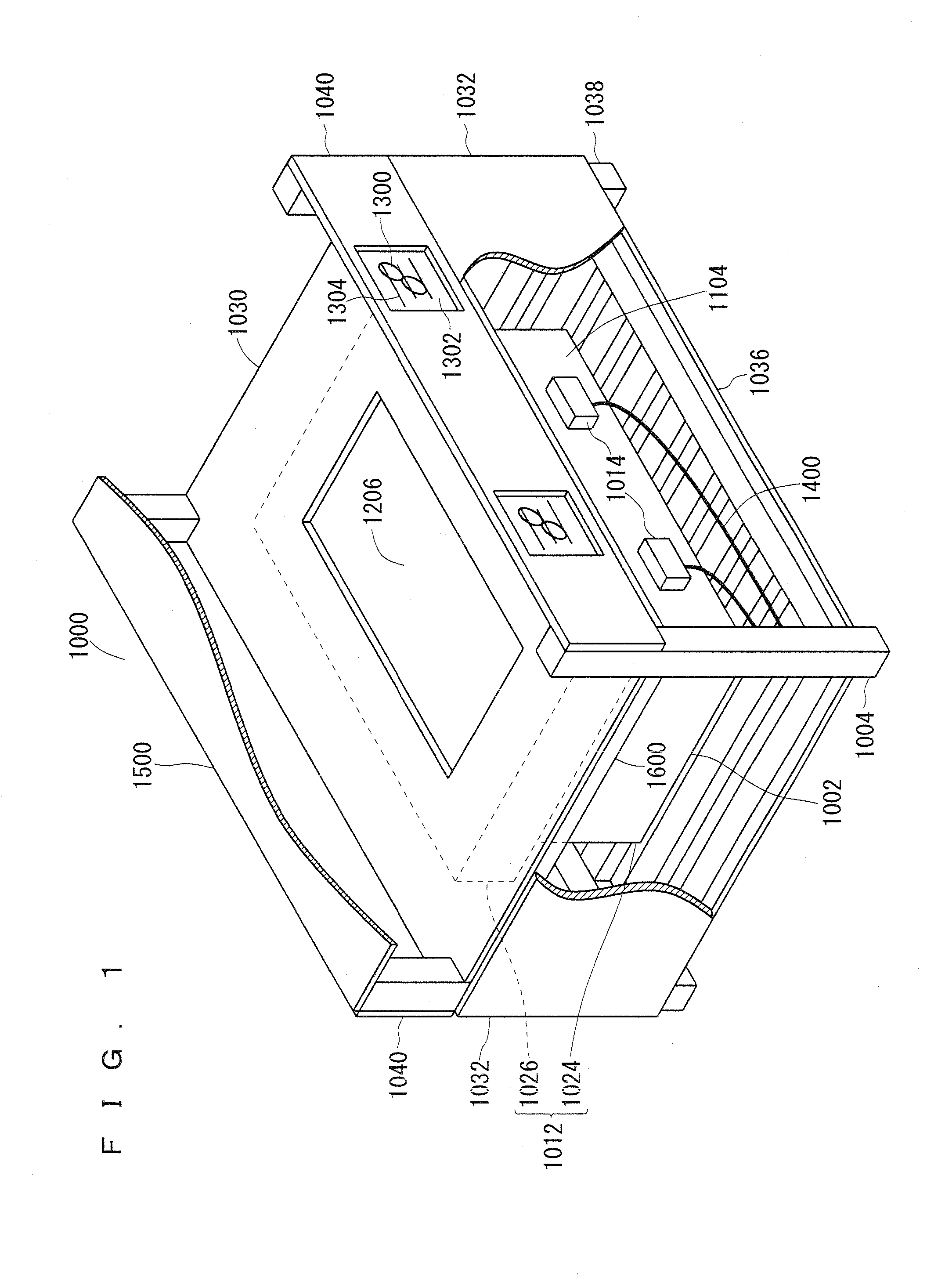
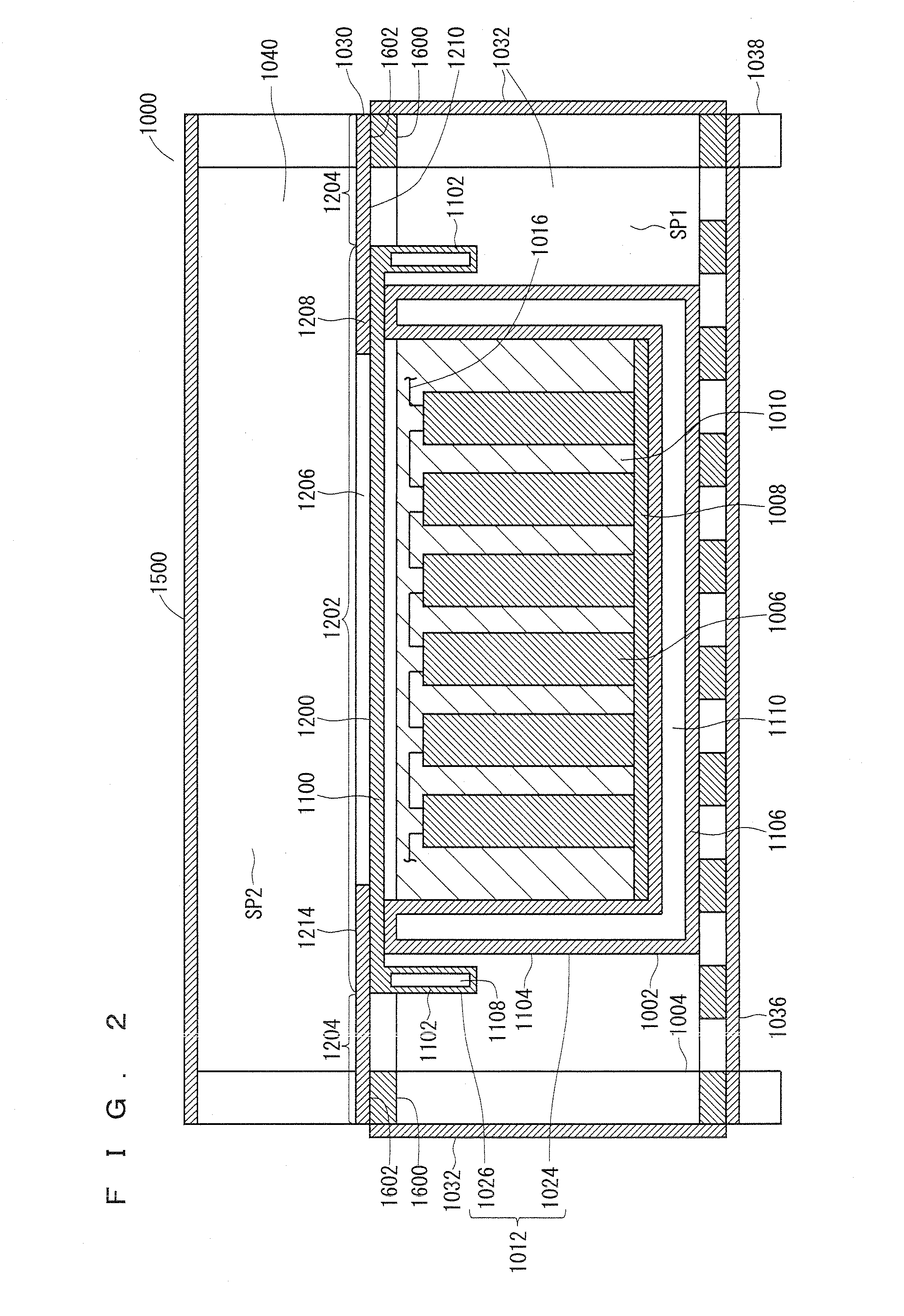
[0036]FIG. 1 and FIG. 2 are schematic views showing the battery housing structure in the first embodiment, wherein FIG. 1 is a perspective view whereas FIG. 2 is a cross-sectional view.

[0037]In a battery housing structure 1000 in the first embodiment, a module battery 1002 is housed in a module battery housing rack 1004, as shown in FIG. 1 and FIG. 2. The module battery 10...

second embodiment

[0070](Outline of Battery Housing Structure)

[0071]A second embodiment relates a battery housing structure that replaces the battery housing structure in the first embodiment.

[0072]FIG. 3 and FIG. 4 are schematic views showing a battery housing structure in the second embodiment, wherein FIG. 3 is a perspective view whereas FIG. 4 is a cross-sectional view.

[0073]A battery housing structure 2000 in the second embodiment is identical to the battery housing structure 1000 in the first embodiment except that a top plate 2030 having no opening is used in place of the top plate 1030 having the opening 1206, as shown in FIG. 3 and FIG. 4. Therefore, in the description of the second embodiment, the same constituents as those in the first embodiment are assigned by the same reference numerals as in the first embodiment, and further, reference is made mainly to matters different from those in the first embodiment. The description of the first embodiment can be applied to matters that are not r...

third embodiment

[0079](Outline of Battery Housing Structure)

[0080]A third embodiment relates a battery housing structure that replaces the battery housing structure in the first embodiment.

[0081]FIG. 5 and FIG. 6 are schematic views showing a battery housing structure in the third embodiment, wherein FIG. 5 is a perspective view whereas FIG. 6 is a cross-sectional view.

[0082]A battery housing structure 3000 in the third embodiment is identical to the battery housing structure 1000 in the first embodiment except that a top plate 3030 having no opening is used in place of the top plate 1030 having the opening 1206 and a thermal conducting medium 3700 is held between a top wall 3100 and a first portion 3202 of the top plate 3030, wherein the top wall 3100 having a rib 3702 formed thereat is used in place of a top wall 1100 having a flat outer surface 1200. Therefore, in the description of the third embodiment, the same constituents as those in the first embodiment are assigned by the same reference nu...


PUM


Abstract

A module battery is housed in a module battery housing rack. An electric cell is housed in a container. The container is provided with a high thermal conductive wall and a low thermal conductive wall. A first portion of a plate overlaps the outer surface of the high thermal conductive wall and a second portion of the plate protrudes from the outer surface. The second portion surrounds the first portion. A first main surface of the plate is brought into direct contact with the outer surface at the first portion and it is apart from the container at the second portion. A second main surface of the plate is exposed to a space, to which heat is allowed to radiate. An opening may or may not be formed at the first portion. A thermal conducting medium may be held between the first wall and the first portion.

Description

TECHNICAL FIELD[0001]The present invention relates to a battery housing structure in a power storage device.BACKGROUND ART[0002]A sodium-sulfur battery needs to be operated at a high temperature. Therefore, the sodium-sulfur battery is used in the state in which an electric cell is housed in a container (i.e., a heat insulating container) together with a heater and the like, as disclosed in Patent Document 1. Here, as referred to in paragraph 0010 of Patent Document 1, since it is undesirable that the inside temperature of the container rises too much, heat is allowed to radiate from the inside of the container to the outside thereof, as required.[0003]On the other hand, a battery (i.e., a module battery) having electric cells for a sodium-sulfur battery housed in a container is used also in the state in which it is housed in a battery housing (i.e., a package), as disclosed in Patent Document 2. In this case, when heat is allowed to radiate from the inside of the container to the o...

Claims


Application Information

Patent Timeline
IPC IPC(8): H01M10/50H01M50/204H01M50/253
CPCH01M10/50H01M10/3909H01M2220/10H01M10/653H01M10/6563H01M10/6554H01M10/617H01M10/627H01M10/6566H01M10/658H01M10/613Y02E60/10H01M50/24H01M50/204H01M50/253
Inventor HATTA, TETSUYATAMAKOSHI, TOMIO
Owner NGK INSULATORS LTD
Why Eureka
Try Eureka