Monitoring Device For Position Monitoring A Robotic Device and Production System Including A Monitoring Device

Inactive Publication Date: 2013-11-07
EROWA
View PDF7 Cites 6 Cited by
  • Summary
  • Abstract
  • Description
  • Claims
  • Application Information

AI Technical Summary

Benefits of technology

[0025]A further object of the invention involves providing a monitoring device by means of which a robotic device of a production system can now be safely operated by reliably preventing executing any prohibited horizontal movements away from the cribs and machine tools by the robotic device and especially the robotic arm.
[0026]The object is achieved by the production system being provided with a monitoring device comprising at least two sensors, a sensor active face being arranged in the zone of the crib to be componented by means of the robotic device or the machine tool to be componented such that the first sensor is activated by each sensor active face when the robotic device is in the loading zone or unloading zone of the corresponding crib or the corresponding machine tool whilst the second sensor is arranged on the robotic device such that a defined horizontal position of the robotic arm, particularly its retracted resting position can be sensed in thus ensuring that the robotic device is capable of executing certain movements only in the zone of a machine tool or a crib.
[0027]In one preferred embodiment of the production system the horizontal extent of each sensor active face is selected so that when the sensor is activated the robotic device can be travelled by a predefine

Problems solved by technology

Where the barrier is arranged within the motion zone of the corresponding robotic device it needs to be sufficiently rugged so that the robotic device, namely the robotic arm or the gripper or workiece cannot penetrate the barrier, as is necessary so that the robotic arm cannot penetrate the barrier because of a malfunction or because of an error in programming or operating the robotic arm.
It is, of course, obvious that the complications involved in such a barrier where very heavy transfer motions are involved are enormous, especially since it is usual that tools and particularly workpieces weighing

Method used


Image

  • Monitoring Device For Position Monitoring A Robotic Device and Production System Including A Monitoring Device
  • Monitoring Device For Position Monitoring A Robotic Device and Production System Including A Monitoring Device
  • Monitoring Device For Position Monitoring A Robotic Device and Production System Including A Monitoring Device

Examples


Example

[0043]It is understood that all parts same to the FIGs. are identified by the same reference numerals.

IMPLEMENTING THE INVENTION

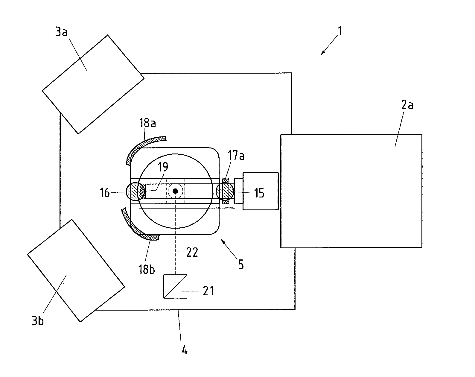
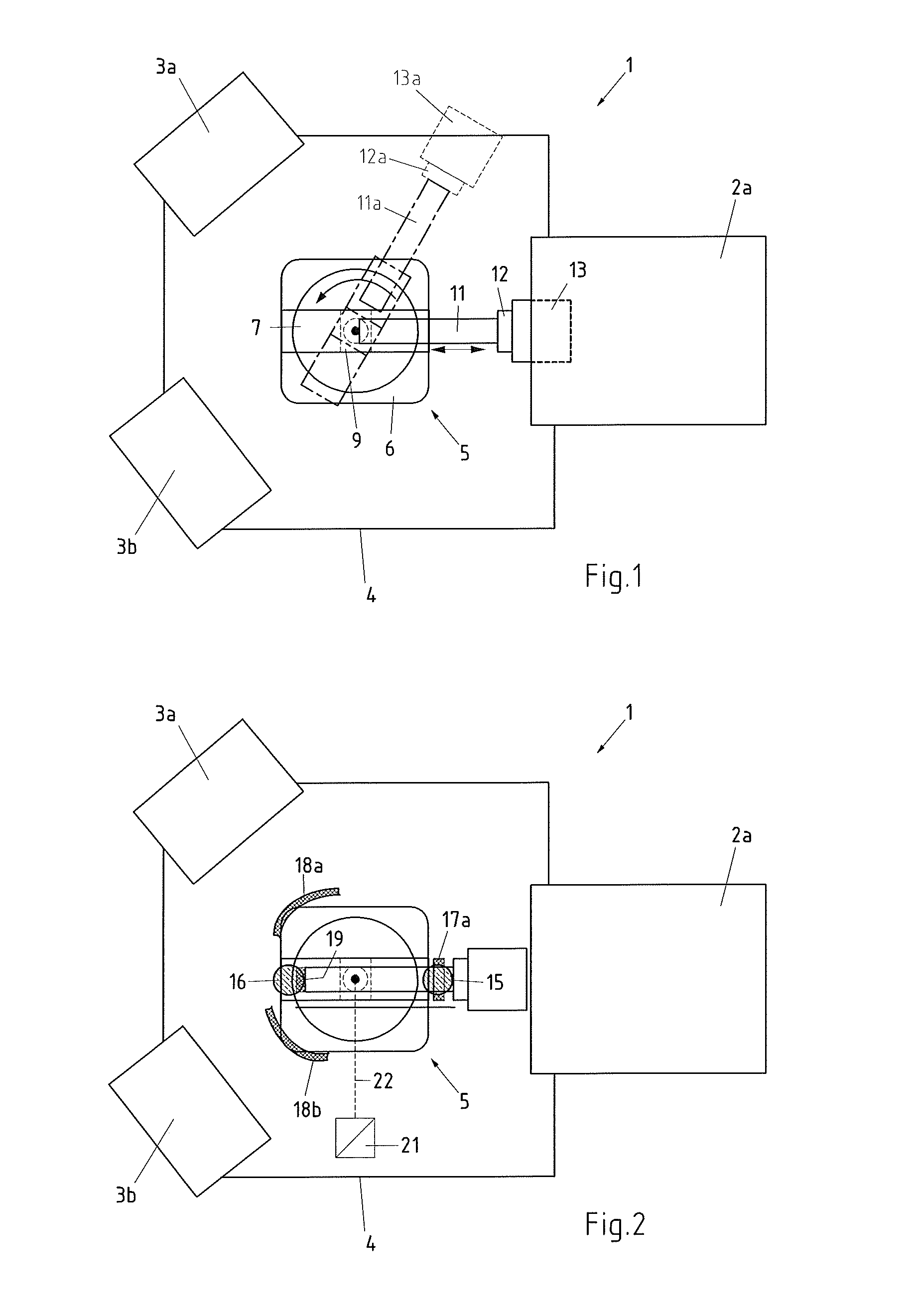
[0044]Referring now to FIG. 1 there is illustrated diagrammatically in a top-down view a production system 1 configured as per prior art. The production system 1 comprises for example a machine tool 2a, two cribs 3a, 3b, a fencing enclosure 4 as well as a robotic device 5. It is understood that the term robotic device is used in each case representative of all embodiments of manipulators.

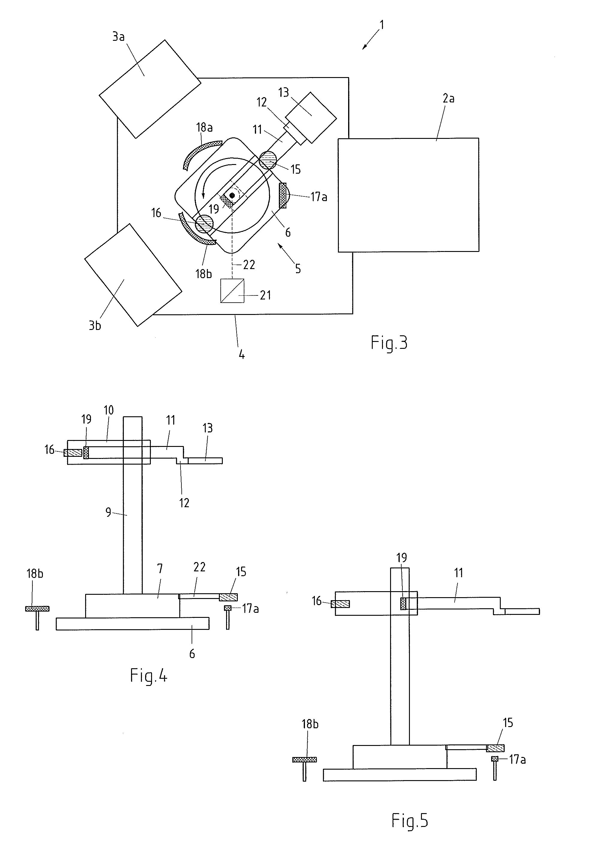
[0045]The cribs 3a, 3b serve to accommodate tools and / or workpieces. The machines involved may be, for example, and not listed conclusively, eroding, milling, grinding, gauging machines or lathes. An example of a suitable robotic device is one having four axes the coupling element—gripper—of which is movable in three translation axes X, Y and Z as well as in the rotational axis C. The robotic device 5 comprises a baseplate 6 on which a main support 9 stands vertically by me...


PUM


Abstract

Proposed is a monitoring device for monitoring and/or sensing predefined positions of a robotic device (5) having at least two axes of motion. The monitoring device comprises at least two sensors (15, 16), the first (15) of which is defined to sense a horizontal position and/or rotative position of the main support (9) and the second sensor (16) a defined horizontal position of the robotic arm (11). The monitoring device comprises furthermore sensor active faces (17a, 18a, 18b) arranged selectively for the first sensor (15) arranged in the horizontal motion zone and/or swivelling zone of the robotic device (5).

Description

FIELD OF THE INVENTION[0001]The invention relates to a monitoring device for monitoring and / or sensing predefined positions of a robotic device having at least two axes of motion, comprising a main support rotatable about a vertical axis (Z axis) and a robotic arm supported thereby. In addition, the invention relates to a production system including one such monitoring device.PRIOR ART[0002]For safe operation of robotic devices, for instance in production systems, precautions must be taken so that any injury to operatives by motion of the robotic device is safely excluded. These precautions involve in addition to active systems such as light barriers, limit switches and the like, mostly also some kind of a barrier in the form of safety fencing. Where the barrier is arranged within the motion zone of the corresponding robotic device it needs to be sufficiently rugged so that the robotic device, namely the robotic arm or the gripper or workiece cannot penetrate the barrier, as is nece...

Claims


Application Information

Patent Timeline
IPC IPC(8): B25J9/16
CPCB25J9/1674Y10S901/49B25J13/089B25J9/041B25J9/101B25J9/1676G05B2219/49137B25J9/10B25J9/06B25J19/02
Inventor HEDIGER, HANS
Owner EROWA
Why Eureka
Try Eureka