Non-invasive roof mounting adaptor and method for installing same

a technology of adapters and roofs, applied in the field of roof mounting adapters, can solve the problems of reducing the service life of roofs, affecting the integrity of roof coverings, and difficult to flash prior art anchor devices, etc., and achieve the effect of minimizing damage and/or crushing

Active Publication Date: 2013-11-14
CORSI PETER A
View PDF0 Cites 61 Cited by
  • Summary
  • Abstract
  • Description
  • Claims
  • Application Information

AI Technical Summary

Benefits of technology

[0012]In yet another aspect, the mounting adapter includes a gap formed between the lower surface of the cover plate and the upper surface of the anchor plate. The gap is formed by a head portion of each first elongated fastener extending upwardly from the upper surface of the anchor plate. In this manner, the lower surface of the cover plate provides a resultant force vector on the head and along the longitudinal axis of each first elongated fastener. That is, the load from the object is preferably transferred though the head and shank of each first elongated fastener to an underlying roofing deck or structure, thereby minimizing damage and / or crushing of the roof membrane and / or roof insulation underneath the present roof mount adapter.

Problems solved by technology

This type of invasive operation compromises the integrity of the roof covering and necessitates some type of roof repair or patching work, which often creates “difficult to flash” penetrations.
Additionally, flashing of the prior art anchor devices 100 frequently cannot be accomplished with roof manufacturer's approved procedures.

Method used


Image

  • Non-invasive roof mounting adaptor and method for installing same
  • Non-invasive roof mounting adaptor and method for installing same
  • Non-invasive roof mounting adaptor and method for installing same

Examples


Embodiment Construction

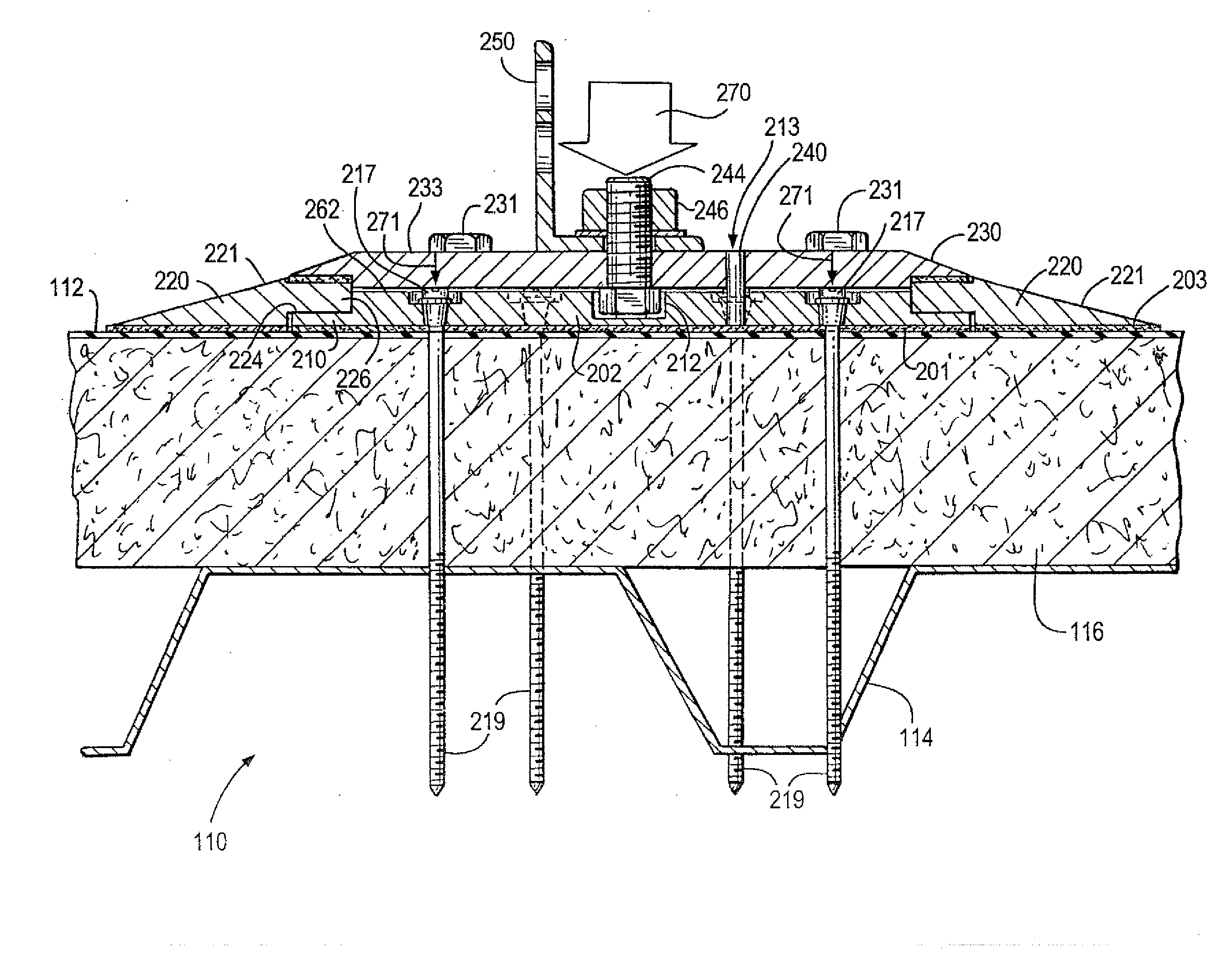
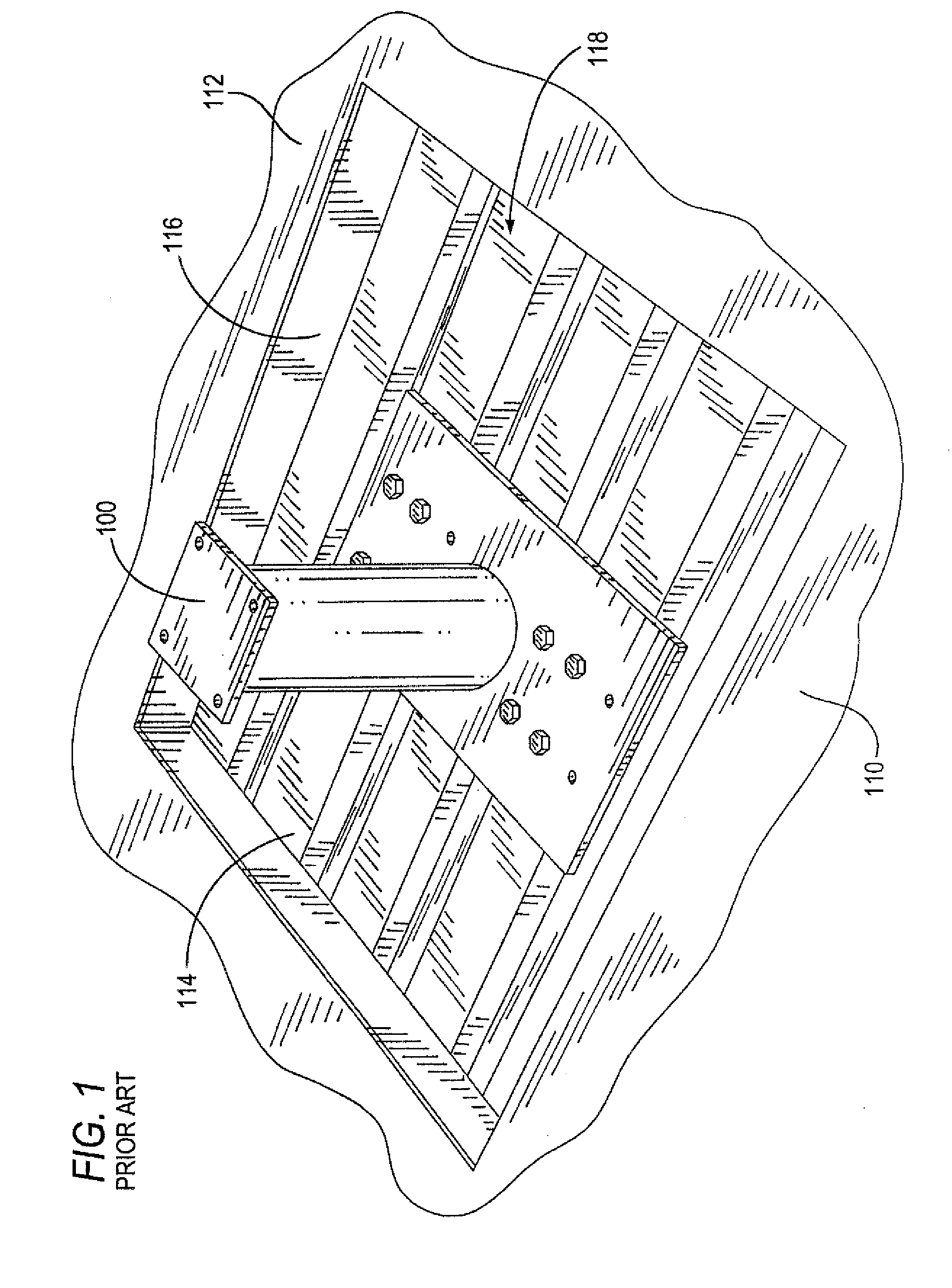
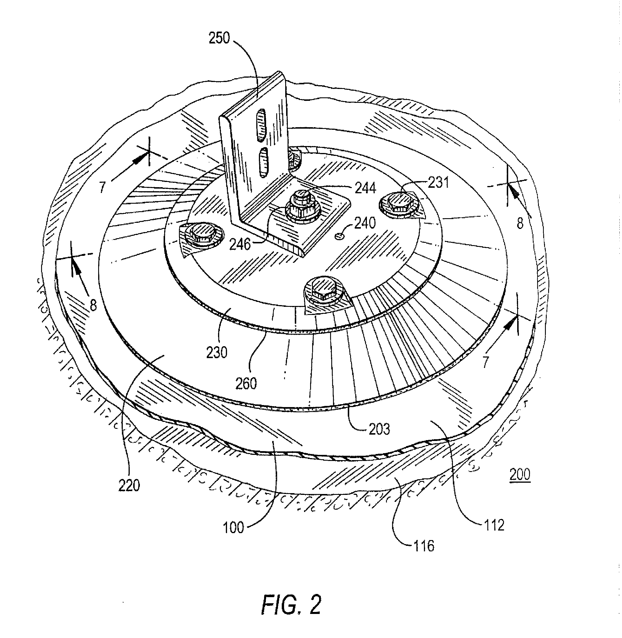
[0036]Referring now to FIGS. 2-8, there is shown a preferred embodiment of a roof mount adapter 200 suitable for use to anchor and otherwise secure equipment and hardware devices to a roof 100 of a building or other edifice or structure (not shown). The roof mount adapter 200 of the present invention is suitable for installation on many different types of roof structures, and is particularly suitable for commercial flat membrane type roofs. Examples of well-known flat or low-sloped membrane roofs include an insulated, multi-ply build-up roof; a single or multi-ply modified Bitumen roof; an insulated single ply, mechanically attached roof; and an insulated, single-ply fully adhered roof. Common to these types of flat style roofs is a lowermost support structure formed by, for example, an 18-22 gauge steel deck 114 of the type illustratively shown in FIG. 1, which is covered by one or more layers of insulation / insulation board 116, and a top cover layer 112 formed by cap sheets or a r...


PUM


Abstract

A mounting adapter for attaching an object to a flat surface includes an anchor plate having a plurality of first apertures extending therethrough. Each first aperture is configured to receive a first elongated fastener having a length sufficient to fasten to a support structure located beneath the surface for attaching the anchor plate thereto. A plurality of threaded apertures is formed in the anchor plate. A cover plate is positioned over the anchor plate and has a plurality of third apertures that align with the plurality of threaded apertures in the anchor plate. A threaded fastener extends through each third aperture and is threadedly engaged with the second threaded apertures of the anchor plate for securely attaching the cover plate to the anchor plate. One or more fourth apertures are formed in the cover plate and configured to receive a third fastener for attaching the object to the mounting adapter.

Description

CROSS-REFERENCE TO RELATED APPLICATION[0001]This patent application claims the benefit of U.S. Provisional Application No. 61 / 645,230, filed May 10, 2012, the content of which is incorporated by reference herein in its entirety.FIELD OF THE INVENTION[0002]The present invention relates to support apparatus, and more specifically to mounting adapters for supporting equipment and hardware devices typically found on a roof top of a building or in direct contact with the ground, and installing the same.BACKGROUND OF THE INVENTION[0003]Commercial and residential buildings often have flat top roofs and / or slightly sloped roof tops, as opposed to high-pitched roofs that are typically observed on many types of residential houses (e.g., colonial, cape, ranch, Tudor and other styles of houses). The flat top roofs on such buildings or other edifices avail themselves for installing various types of equipment that are used by the owners and / or tenants of the buildings. Such “equipment” can includ...

Claims


Application Information

Patent Timeline
Patent Type & Authority Applications(United States)
IPC IPC(8): E04B1/41
CPCE04B1/40Y02B10/20Y02E10/47H02S20/24F24S25/61F24S2025/021Y02E10/50Y02B10/10F24S25/615F24S25/617E04B1/388
Inventor CORSI, PETER A.
Owner CORSI PETER A
Why Eureka
Try Eureka