
Three-Dimensional Shape Measurement Method and Three-Dimensional Shape Measurement Device

a three-dimensional shape and measurement method technology, applied in the direction of instruments, holographic light sources/light beam properties, holographic processes, etc., can solve the problems of not being able to apply to a rough surface object which emits scattered lights, and the accuracy of measurement is remarkably affected by a speckle noise, so as to achieve highly precise three-dimensional measurement and reduce the influence of speckle nois

Inactive Publication Date: 2013-11-14
UNIV OF HYOGO
View PDF2 Cites 34 Cited by
  • Summary
  • Abstract
  • Description
  • Claims
  • Application Information

AI Technical Summary

Benefits of technology

[0022]According to the three-dimensional shape measurement method of the present invention, because an interference fringe pattern having a single spatial frequency is extracted from a hologram in which a projected image is recorded and to which a focusing method is applied, the influence of the noise due to speckles is reduced or eliminated, and highly precise three-dimensional measurement can be realized. Moreover, because this

Problems solved by technology

However, the measurement method using the shape-from-focus method shown in the patent document 1 mentioned above is applied to as measuring objects parts which reflect lights like a mirror or a lens, and therefore it is not applicable to a rough surf

Method used


Image

  • Three-Dimensional Shape Measurement Method and Three-Dimensional Shape Measurement Device
  • Three-Dimensional Shape Measurement Method and Three-Dimensional Shape Measurement Device
  • Three-Dimensional Shape Measurement Method and Three-Dimensional Shape Measurement Device

Examples


Embodiment Construction

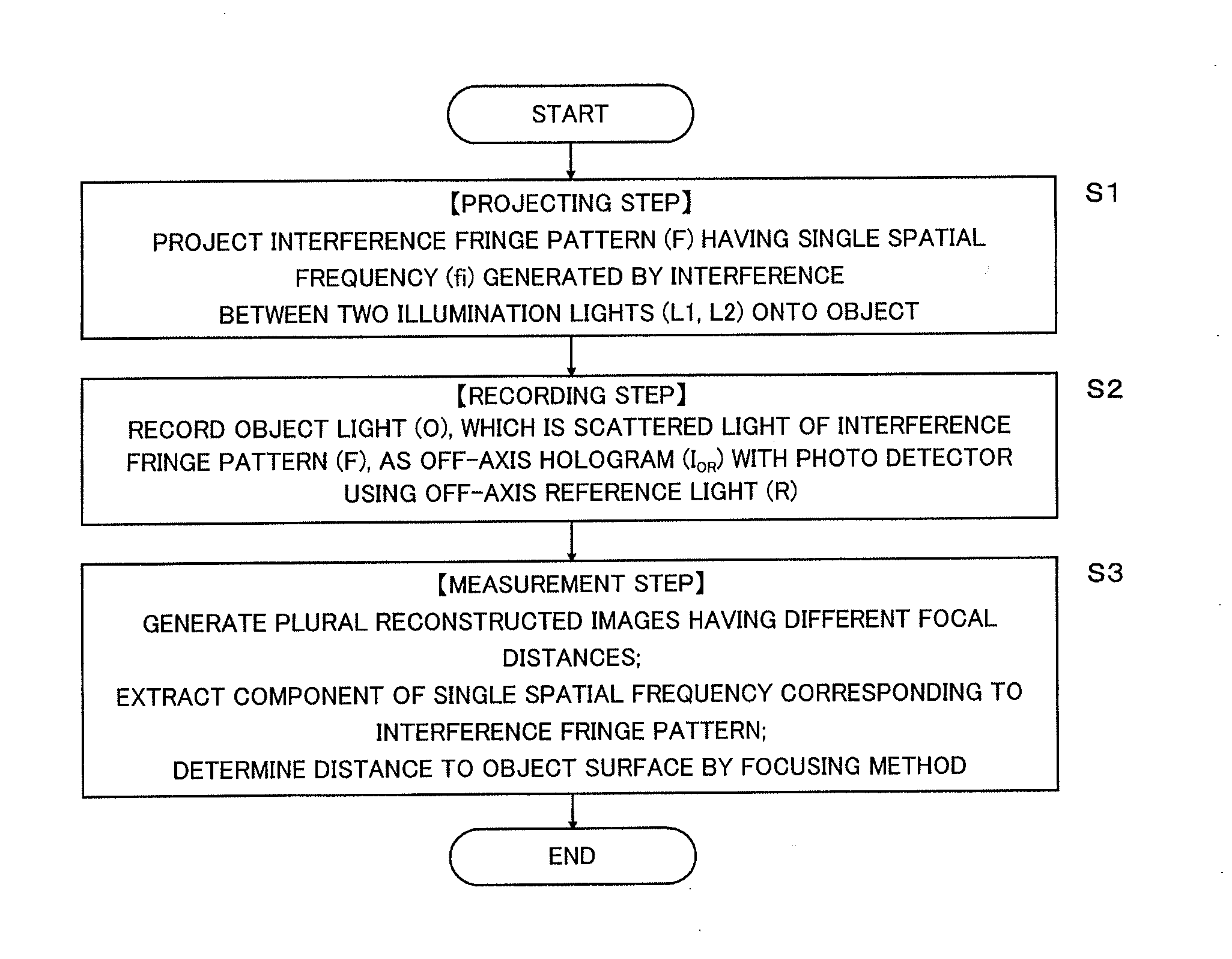
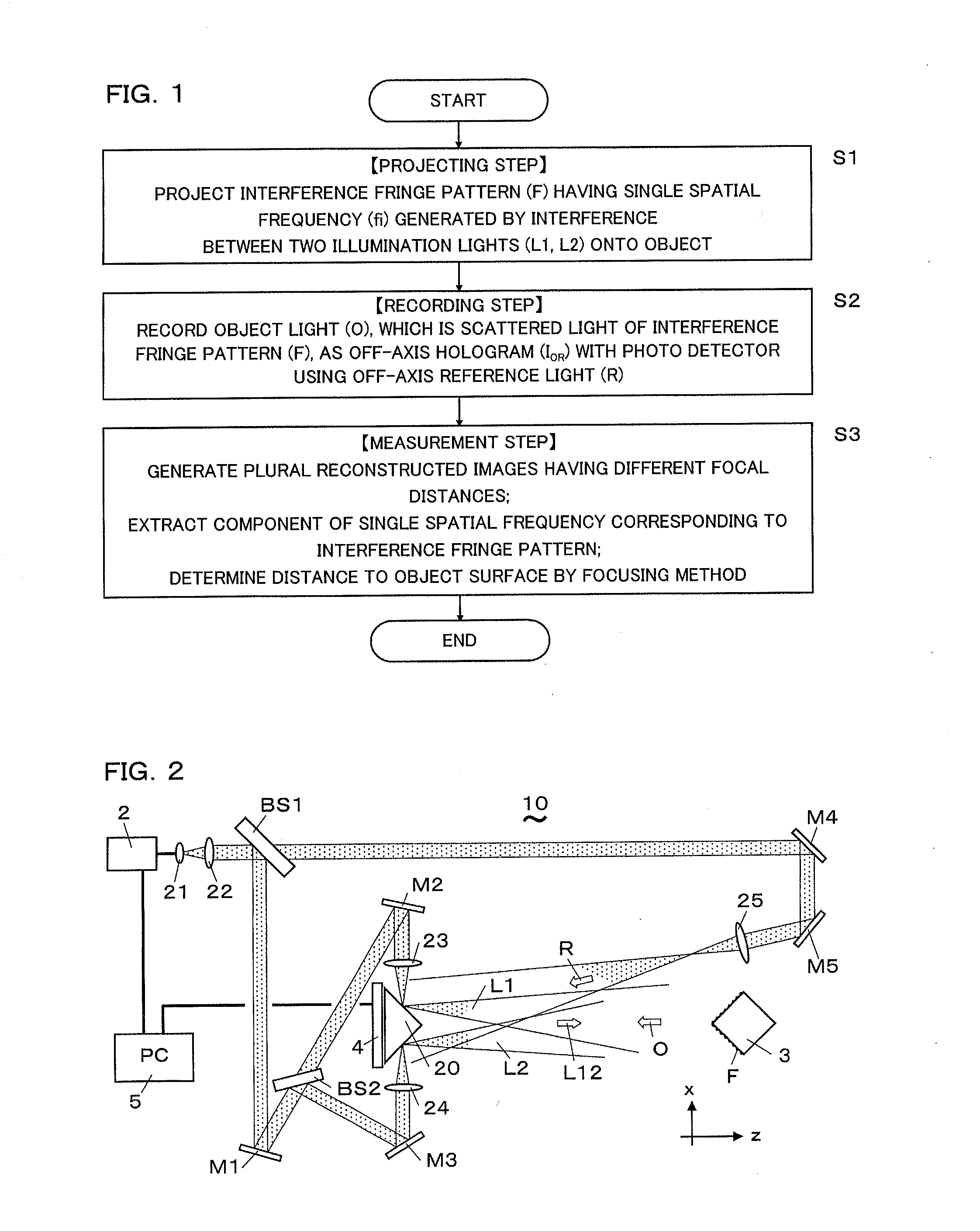
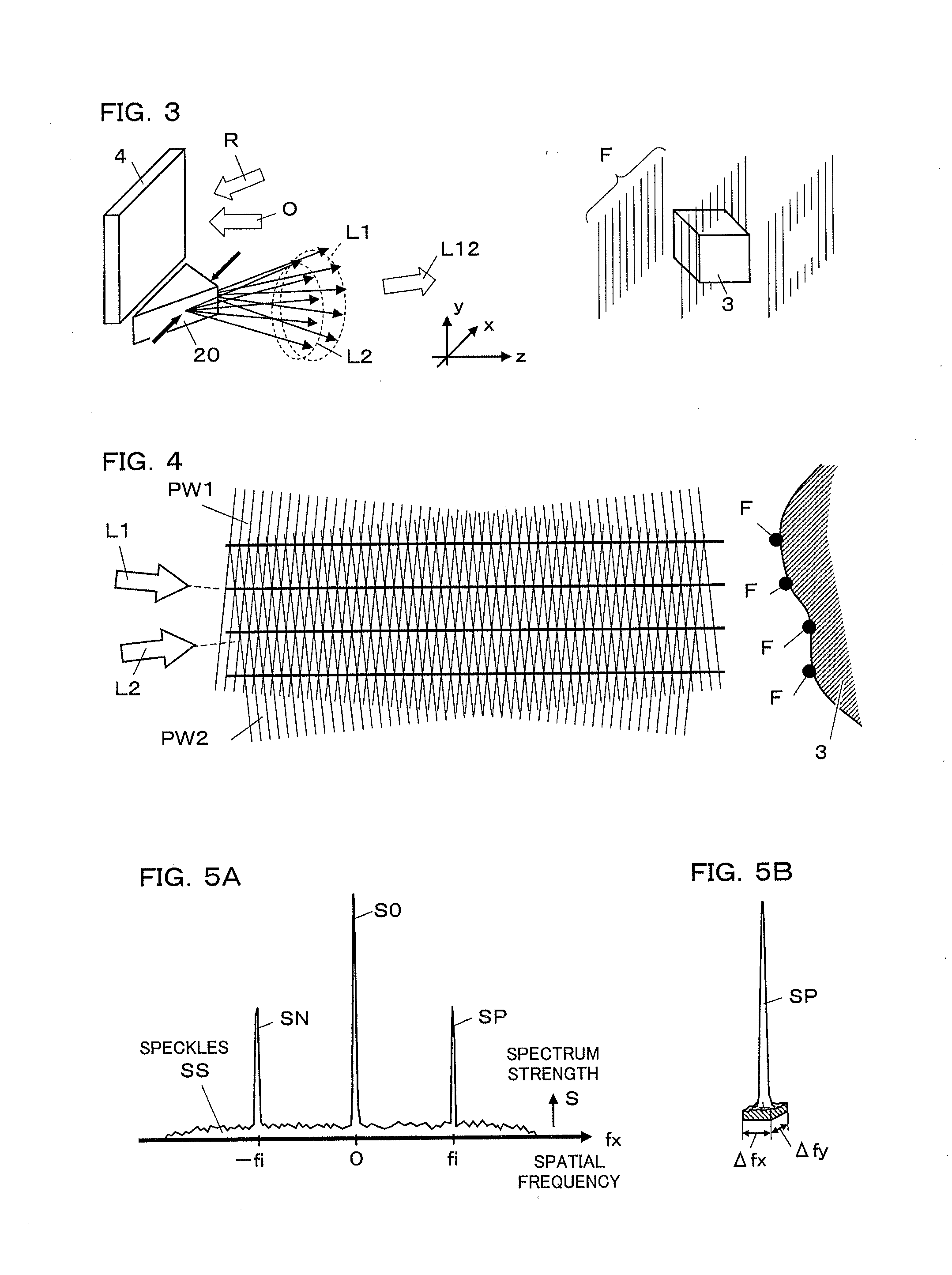
[0048]Hereafter, a method for measuring a three-dimensional shape and a device for measuring a three-dimensional shape (hereafter called as the measurement method or the measurement device, etc.) of the present invention are described with reference to drawings. FIGS. 1 to 12 show the measurement method and device according to an embodiment of the present invention. As shown in a flow chart of FIG. 1, the measurement method of the present invention is a method for measuring a three-dimensional shape of an object surface using a digital hologram in which an interference fringe pattern F projected onto the object surface is recorded, and comprises a projection step (S1), a recording step (S2), and a measurement step (S3). In the projection step (S1), the interference fringe pattern F, which has a single spatial frequency fi generated by interference between two illumination lights L1 and L2, is projected onto the object. In the recording step (S2), an object light O which is a scatter...


PUM


Abstract

This three-dimensional shape measurement method comprises: a projection step for projecting an interference fringe pattern (F) having a single spatial frequency (fi) onto an object surface; a recording step for recording the pattern (F) as a digital hologram; and a measurement step for generating a plurality of reconstructed images having different focal distances from the hologram, and deriving the distance to each point on the object surface by applying a focusing method to the pattern (F) on each of the reconstructed images. The measurement step extracts the component of the single spatial frequency (fi) corresponding to the pattern (F) from each of the reconstructed images by spatial frequency filtering, upon applying the focusing method, and makes it possible to achieve a highly accurate measurement in which the adverse effect of speckles is reduced and the advantage of a free-focus image reconstruction with holography is used effectively.

Description

TECHNICAL FIELD[0001]The present invention relates to a method for measuring a three-dimensional shape and a device for measuring a three-dimensional shape using digital holography.BACKGROUND ART[0002]Conventionally, various optical three-dimensional measurement methods applied to a rough surface object are known as a method for measuring a shape of an object surface by non-contact. For example, some methods are known which use a lattice image distorted by a target object from an original lattice pattern projected onto the object with a projector. Followings are included in these methods: a moire method taking a picture of the lattice image as a moire image (contour line); a phase shifting method taking a picture of the lattice image by changing the phase of light; and a spatial code method deriving space coordinates for groups of points distributed on a surface from focus locations in an image. Furthermore, a spot light method which takes an image of spots on an object illuminated ...

Claims


Application Information

Patent Timeline
IPC IPC(8): G06T7/60
CPCG06T7/60G01B11/25G03H1/0443G03H1/0866G03H2001/0445G03H2210/30G03H2210/62G03H2222/35G03H2222/44G03H2223/18G03H2001/0033
Inventor SATO, KUNIHIRO
Owner UNIV OF HYOGO
Learn More