
Phase shifting coding method

A technology of phase shift coding and coding method, which is applied to measurement devices, instruments, and optical devices, etc., can solve the problems of difficult determination of fringe order, errors at jumps, and periodic dislocations.

Active Publication Date: 2014-02-12
NANCHANG HANGKONG UNIVERSITY
View PDF4 Cites 24 Cited by
  • Summary
  • Abstract
  • Description
  • Claims
  • Application Information

AI Technical Summary

Problems solved by technology

[0007] The purpose of the present invention is to provide a phase-shift encoding method, which can well solve the problems of difficult judgment of fringe levels, errors at transitions and period misalignment in the case of defocusing, and realize various light and dark levels. High-precision three-dimensional measurement of objects, with high practical value

Method used

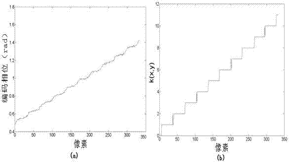
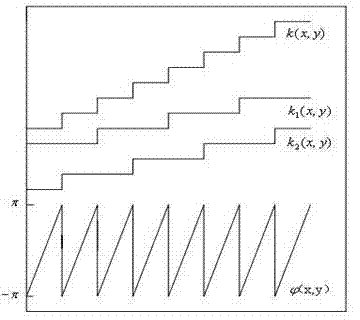

Image

  • Phase shifting coding method
  • Phase shifting coding method
  • Phase shifting coding method

Examples


Embodiment Construction

[0018] (1) The principle of the phase shift encoding method: for any periodic signal , the result of phase shift encoding, B=F[ , ,…, ], n Indicates the number of phase shift steps, such as two-step, three-step, four-step phase shift; Indicates the phase shift step size; the function F[ A ( φ ), ,…, ] indicates a phase-shifted signal , ,…, Any operation between them can be addition, subtraction, or, XOR, and can also be a specified operation; during operation, only some of the phase shift signals can be selected according to the needs, and the phase shift coding method and the periodic signal , phase shift step size, phase shift step number and function F are related, by changing the phase shift step size, phase shift step number and the operation represented by function F, the periodic signal can be adjusted according to actual requirements Perform arbitrary coding to realize various functions.

[0019] (2) Based on the phase shift coding method k (x...


PUM


Abstract

The invention discloses a phase shifting coding method. The phase shifting coding method is composed of three major key technologies including the principle of the phase shifting coding method, the k (x, y) coding method based on the phase shifting coding method and the k (x, y) calibration and periodicity dislocation calibration method based on the phase shifting coding method. The phase shifting coding method has the advantages that the strip level k (x, y) judging problem caused by defocus along with the increase of the phase coding strip periodicity can be solved; errors occurring in the time hopping part of the strip level k (x, y) can be solved, and the strip level calibration is achieved; the problem of the periodicity dislocation of truncation phase and the strip level can be solved. The phase shifting coding method is convenient to operate, high-precision three-dimensional measurement of a complex object can be achieved, and the phase shifting coding method has very high practical value.

Description

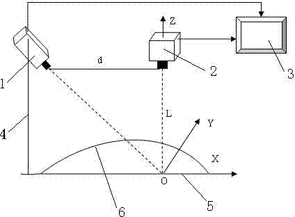
technical field [0001] The invention relates to a phase shift encoding method, in particular to a phase shift encoding method proposed on the basis of the phase encoding method. Background technique [0002] Fringe projection profilometry is of great significance in three-dimensional measurement due to its advantages of non-contact, full-field measurement, fast measurement speed and easy information processing. 3D measurement systems such as figure 1 , comprising a projector 1, a video camera 2, a computer 3, a measuring support 4, and a reference plane 5; it is characterized in that: the projector 1 and the video camera 2 are placed on the measuring support 4; the projector 1 and the video camera 2 are respectively connected to the computer 3 with wires; The object 6 to be measured is placed on the reference plane 5; the computer 3 includes an image acquisition card, projection software, and measurement software. The projector 1 projects the stripes with characteristic in...

Claims


Application Information

Patent Timeline
IPC IPC(8): G01B11/25
Inventor 伏燕军王志刚杨杰
Owner NANCHANG HANGKONG UNIVERSITY
Learn More