
A kind of diffractive optical element and its preparation method

A diffractive optical element and light source technology, applied in optical elements, optics, instruments, etc., can solve problems such as reducing the uniformity of spot patterns

Active Publication Date: 2019-12-13
SHENZHEN ORBBEC CO LTD
View PDF9 Cites 1 Cited by
  • Summary
  • Abstract
  • Description
  • Claims
  • Application Information

AI Technical Summary

Problems solved by technology

However, in order to improve the calculation accuracy, that is, to ensure uniform spot density distribution, the arrangement of VCSEL array chips and the randomness of sub-spot patterns will reduce the uniformity of the final projected spot pattern

Method used

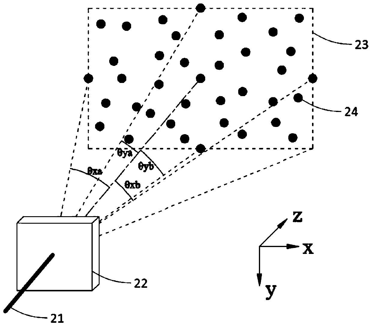
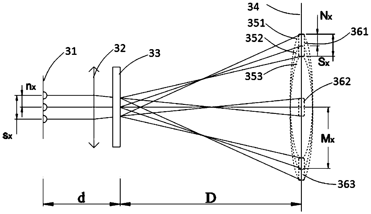

Image

  • A kind of diffractive optical element and its preparation method
  • A kind of diffractive optical element and its preparation method
  • A kind of diffractive optical element and its preparation method

Examples


Embodiment Construction

[0046] Embodiments of the present invention will be described in detail below. It should be emphasized that the following description is only exemplary and not intended to limit the scope of the invention and its application.

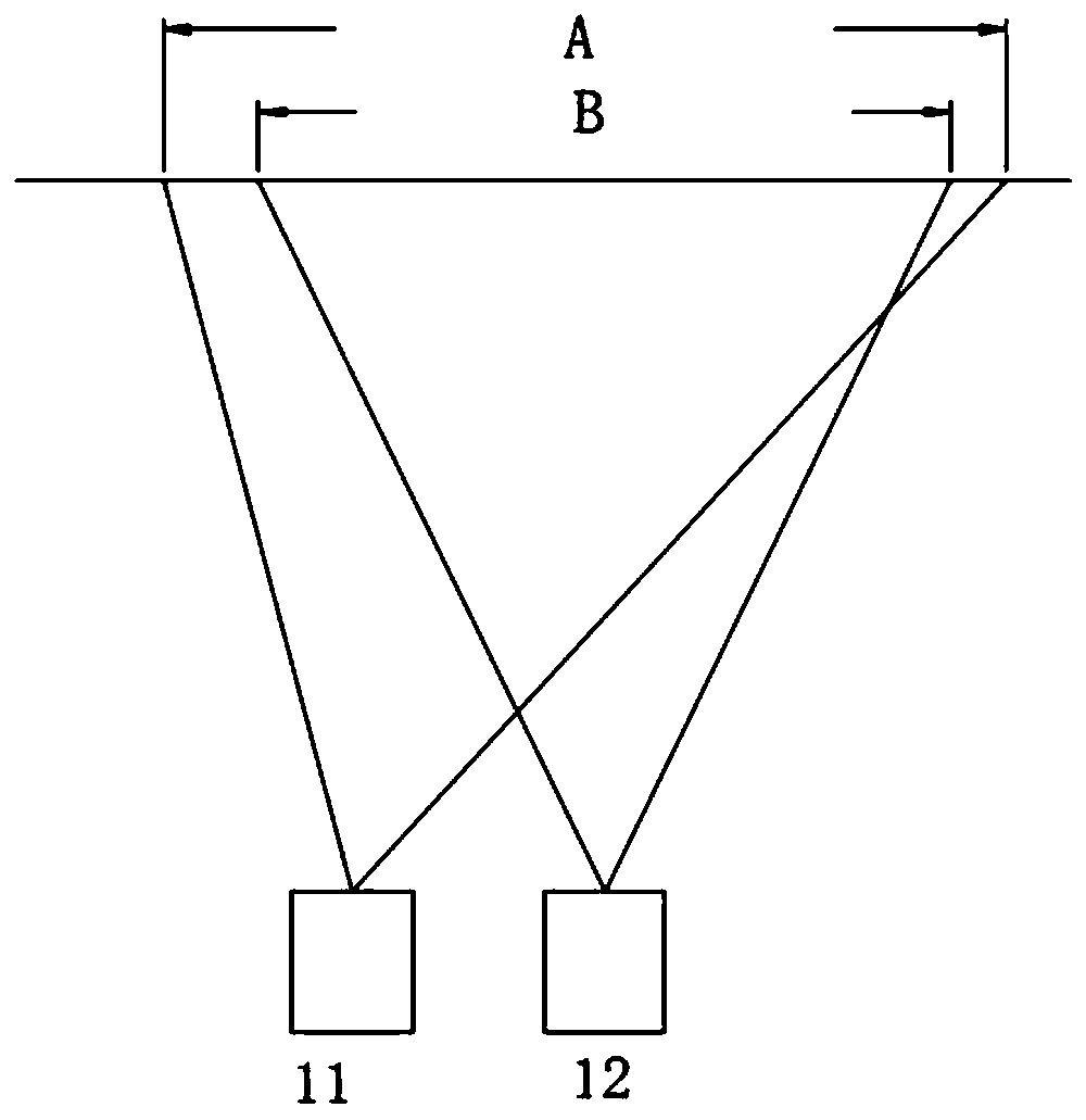
[0047] figure 1 It is a schematic diagram of a depth camera based on structured light technology. The depth camera includes a structured light projection module 11 and an acquisition module 12. The structured light projection module is used to project structured light patterns into the spatial projection area A, and the acquisition module is used to acquire structured light images on objects in its acquisition area B , generally the projection area A is not lower than the collection area B, so as to ensure that the objects in the collection area corresponding to the collection module can be covered by the structured light pattern. In addition, the depth camera also includes a processor for receiving the structured light image collected by the collecti...


PUM


Abstract

The invention discloses a diffractive optical element, which is used in a structured light projection module. The structured light projection module includes: a light source, including a plurality of sub-light sources arranged in a two-dimensional array, for emitting A two-dimensional patterned beam; a diffractive optical element that receives the two-dimensional patterned beam and generates a multi-level diffracted beam; wherein the diffractive optical element is configured to project a plurality of non-overlapping two-dimensional patterned beams, Each two-dimensional patterned light beam corresponds to generate a replicated pattern, and multiple non-overlapped replicated patterns form a spot pattern with uniform density distribution. Also disclosed is a method of using the diffractive optical element to prepare a structured light projection module. According to the present invention, the diffractive optical element is prepared for the structured light projection module, which can project a combined speckle pattern with uniform density distribution under the condition of satisfying the irrelevance.

Description

technical field [0001] The invention relates to a diffractive optical element and a method for preparing a structured light projection module by using the diffractive optical element. Background technique [0002] 3D imaging technology is the core of the new generation of human-computer interaction technology. With the rigid demand of mobile terminal equipment for 3D imaging technology, depth cameras will be widely used in mobile terminal equipment, which also makes depth cameras move towards low power consumption. , high performance, and small volume. The structured light projection module is the core device in the depth camera based on structured light technology, and its main components are light source and diffractive optical element (DOE). Diffractive Optical Elements (DOE) have the function of modulating light beams, such as splitting incident light beams to generate outgoing light beams with specific structured patterns. A typical solution is to use a laser emitter ...

Claims


Application Information

Patent Timeline
Patent Type & Authority Patents(China)
IPC IPC(8): G02B27/42G02B27/09G03B35/00
CPCG02B27/0944G02B27/4233G02B27/425G02B27/4266G02B27/4272G02B27/4277G03B35/00G02B27/48G02B27/4205
Inventor 许星
Owner SHENZHEN ORBBEC CO LTD
Learn More