Connector

Active Publication Date: 2013-11-14
JAPAN AVIATION ELECTRONICS IND LTD
View PDF5 Cites 14 Cited by
  • Summary
  • Abstract
  • Description
  • Claims
  • Application Information

AI Technical Summary

Benefits of technology

[0010]As for the connector according to the present invention, the regulating portion, which extends in a direction (intersecting direction) intersecting with the predetermined direction, is received in the regulated portion along the predetermined direction. Accordingly, not an end surface but a side portion of the regulating portion is received in the regulated portion.
[0011]The connector according to the present invention is configured as described above so that the regulating portion may be easily inserted into the regulated portion when the side portion of the regulating portion is formed to have a large size relative to the regulated portion in the intersecting direction. Moreover, the regulating portion, which is received in the regulated por

Problems solved by technology

It is very dangerous if a mated state, where the connector and the mating connec

Method used


Image

  • Connector
  • Connector
  • Connector

Examples


Example

[0027]While the invention is susceptible to various modifications and alternative forms, specific embodiments thereof are shown by way of example in the drawings and will herein be described in detail. It should be understood, however, that the drawings and detailed description thereto are not intended to limit the invention to the particular form disclosed, but on the contrary, the intention is to cover all modifications, equivalents and alternatives falling within the spirit and scope of the present invention as defined by the appended claims.

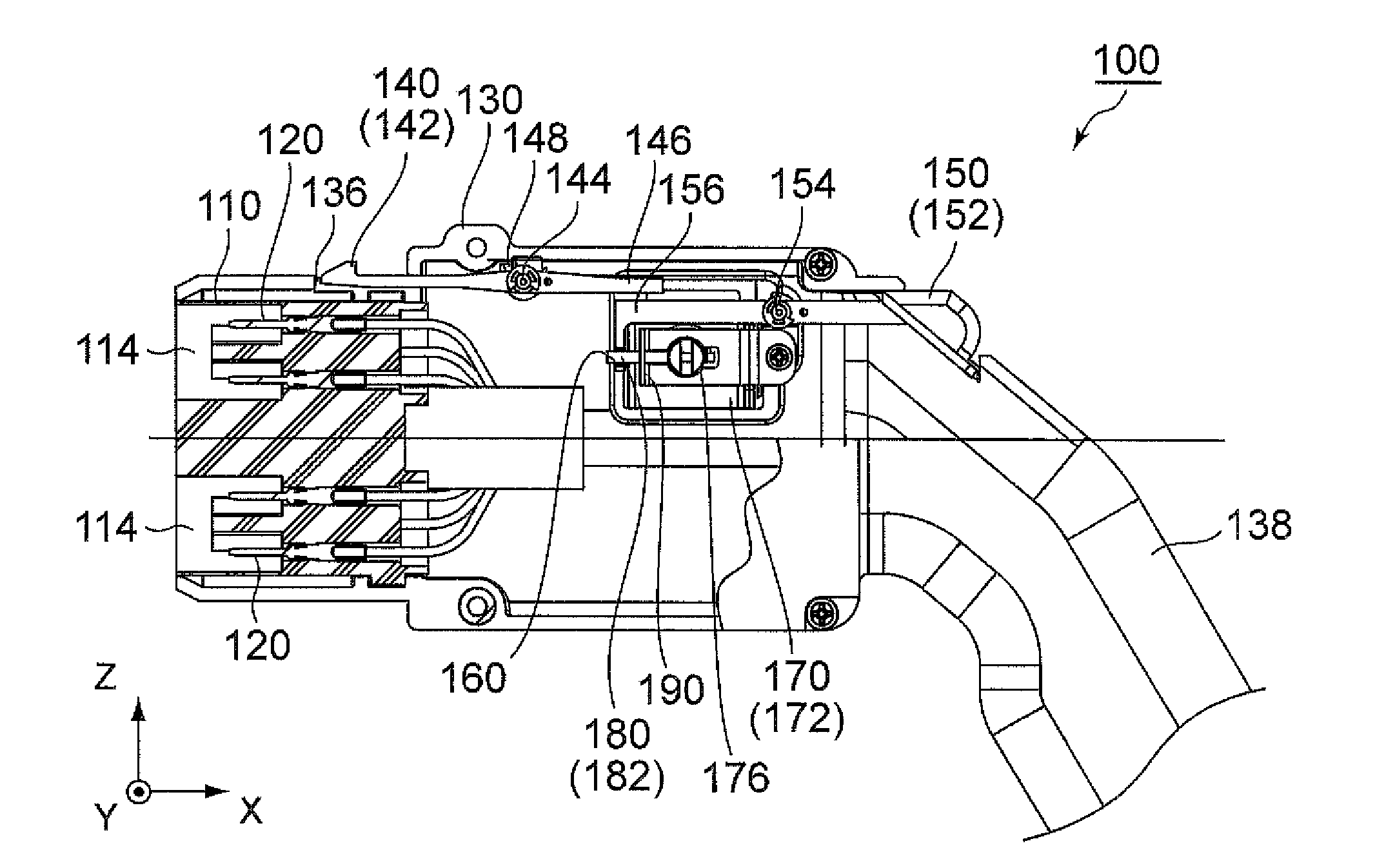
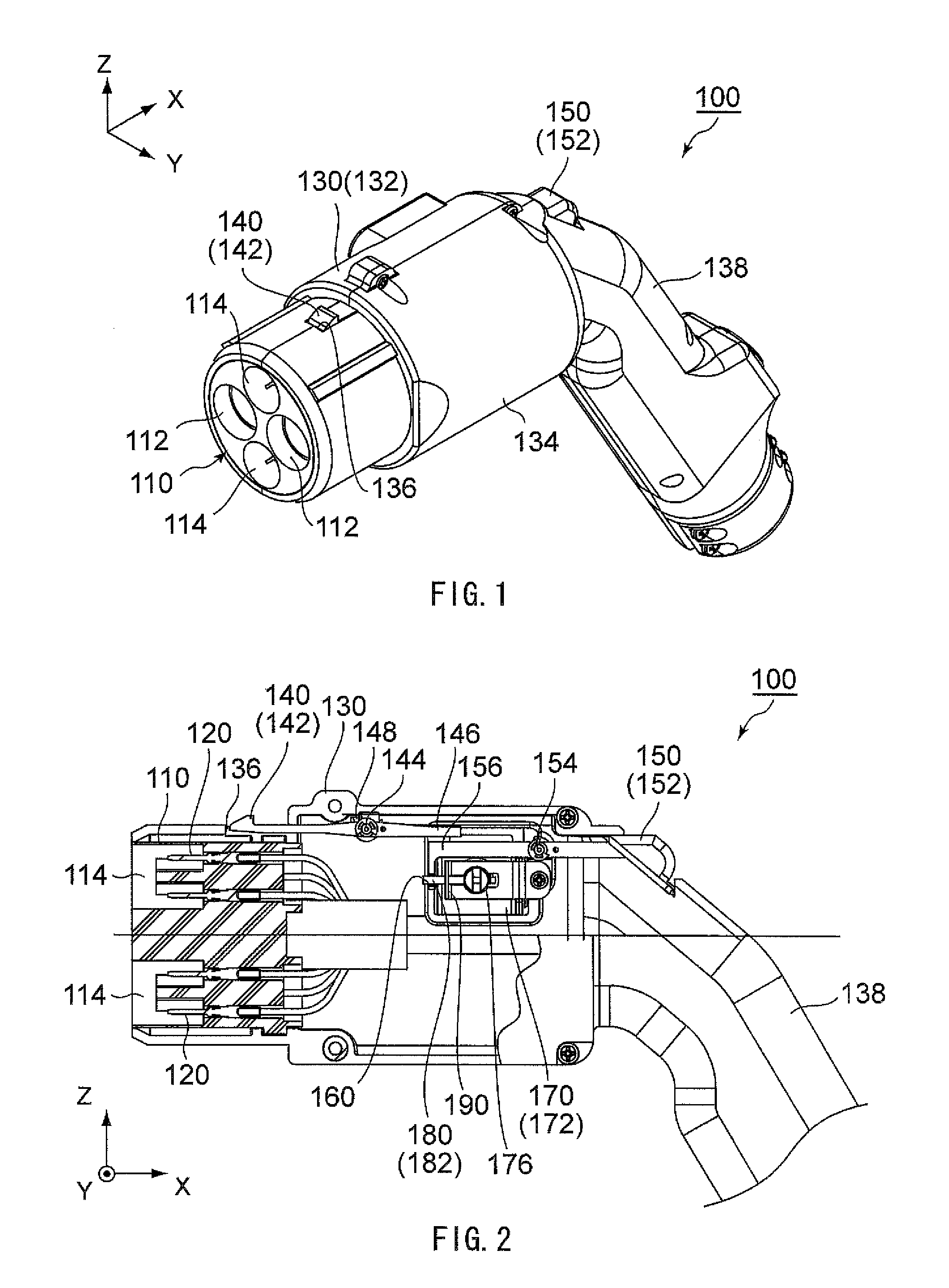
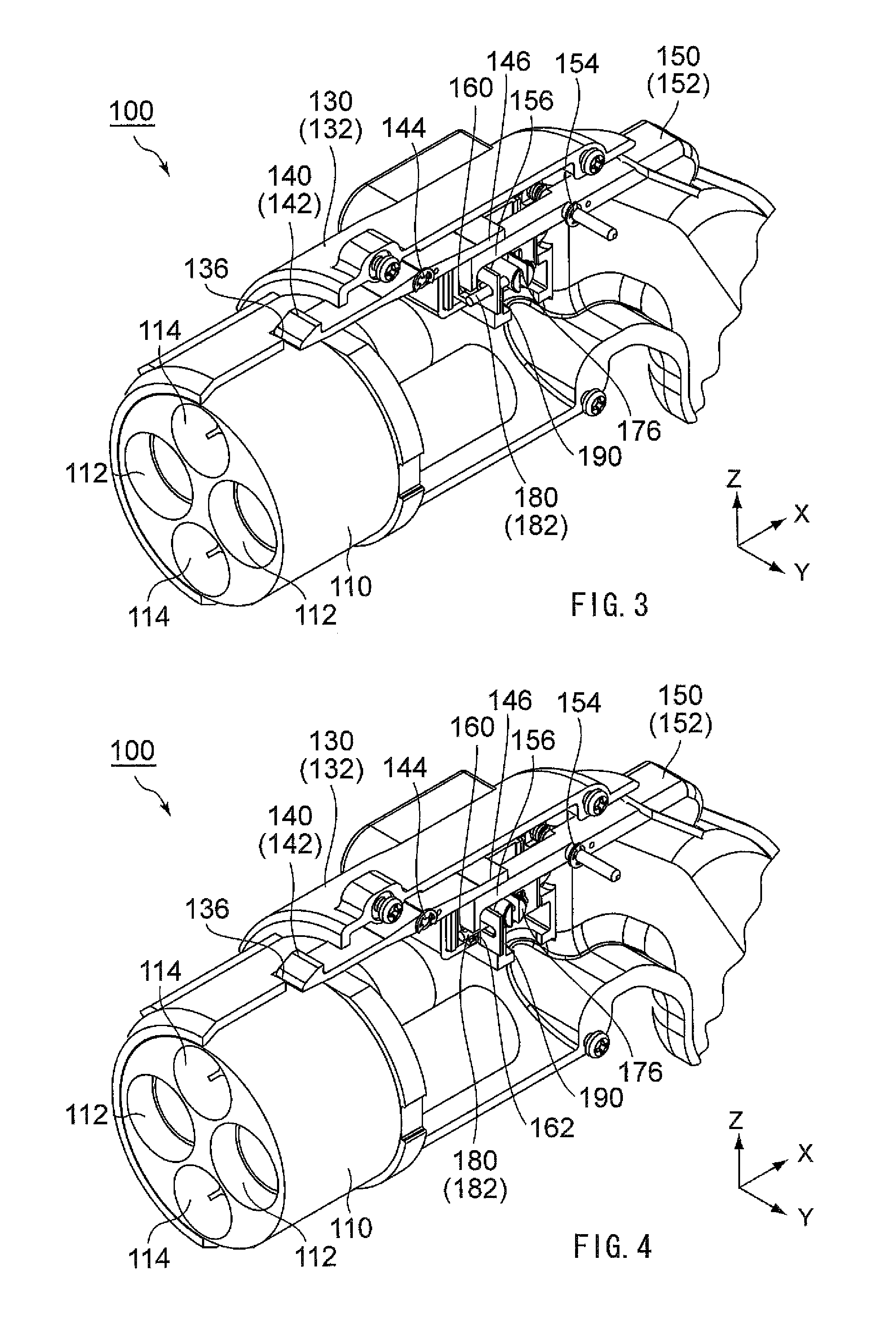
[0028]As shown in FIGS. 1 to 4, a connector 100 according to an embodiment of the present invention is a power-supply plug. The connector 100 is mateable along the X-direction (mating direction) with a mating connector (power-receiving receptacle) 200 (see FIGS. 10 and 11) installed, for example, in an electric car.

[0029]As shown in FIGS. 10 and 11, the mating connector 200 comprises a housing 210 made of an insulating material, a plurality o...


PUM


Abstract

A connector capable of being fitted to a partner connector is provided with a lock member, a solenoid having a plunger, a restriction member having a restricting part, and a restricted part. In a fitted state in which the connector and the partner connector are fitted to each other, the lock member engages the partner connector and locks the two connectors into a fitted state. The solenoid drives the plunger between a restriction position and a release position. The restriction member is movably supported by the plunger. The restricted part receives the restricting part when the plunger is driven into the restriction position. When the plunger is in the restriction position, movement of the restricted part is restricted by the restricting part, and thereby the restricted part directly or indirectly prevents release of the fitted state.

Description

TECHNICAL FIELD[0001]This invention relates to a connector which is used to supply electric power, for example, to an electric car.BACKGROUND ART[0002]A connector, which is used to supply electric power, is provided with a power pin or a power contact for supplying high electric current. While the electric power is supplied, high electric current flows from the connector to a mating connector, which is mated with the connector, through the power pin or the power contact. It is very dangerous if a mated state, where the connector and the mating connector are mated with each other, is released while the electric power is supplied. Therefore, this type of connectors is generally provided with a structure which prevents the mated state from being released when the electric power is supplied.[0003]For example, the connector provided with the aforementioned structure is disclosed in Patent Document 1 or Patent Document 2, contents of which are incorporated herein by reference. The connect...

Claims


Application Information

Patent Timeline
IPC IPC(8): H01R13/62
CPCH01R13/62H01R13/6275B60L2270/32B60L2270/34Y02T90/14H01R13/6397H01R2201/26H01R13/6633Y02T10/7072B60L53/16Y02T10/70
Inventor TAKAGI, YOHEIOTSUKA, YOSHIROHASHIGUCHI, OSAMU
Owner JAPAN AVIATION ELECTRONICS IND LTD
Why Eureka
Try Eureka