Air feed structure for vehicle

a technology for air feed and vehicles, which is applied to vehicle components, vehicle heating/cooling devices, transportation and packaging, etc., can solve the problems of increasing the size difficult to dispose of the blowing portion in a narrow space, and insufficient reduction of parts, so as to and improve the rigidity of the fixing portion

Inactive Publication Date: 2013-11-14
SUZUKI MOTOR CORP
View PDF24 Cites 18 Cited by
  • Summary
  • Abstract
  • Description
  • Claims
  • Application Information

AI Technical Summary

Benefits of technology

[0026]In the present invention, when the longitudinal fin is formed integrally with a pair of lateral fins adjacent to each other above and below in such a way as to couple the pair of lateral fins, the following effect can be produced.
[0027]The rigidities of the lateral fins can be improved.
[0028]In the present invention, when the air blowing portion is disposed at a side portion of an instrument panel and a fixing portion, which is to be fixed to a fixed portion disposed at the instrument panel, is disposed at a periphery of the convex portion of the air feed duct, the following effect can be produced.
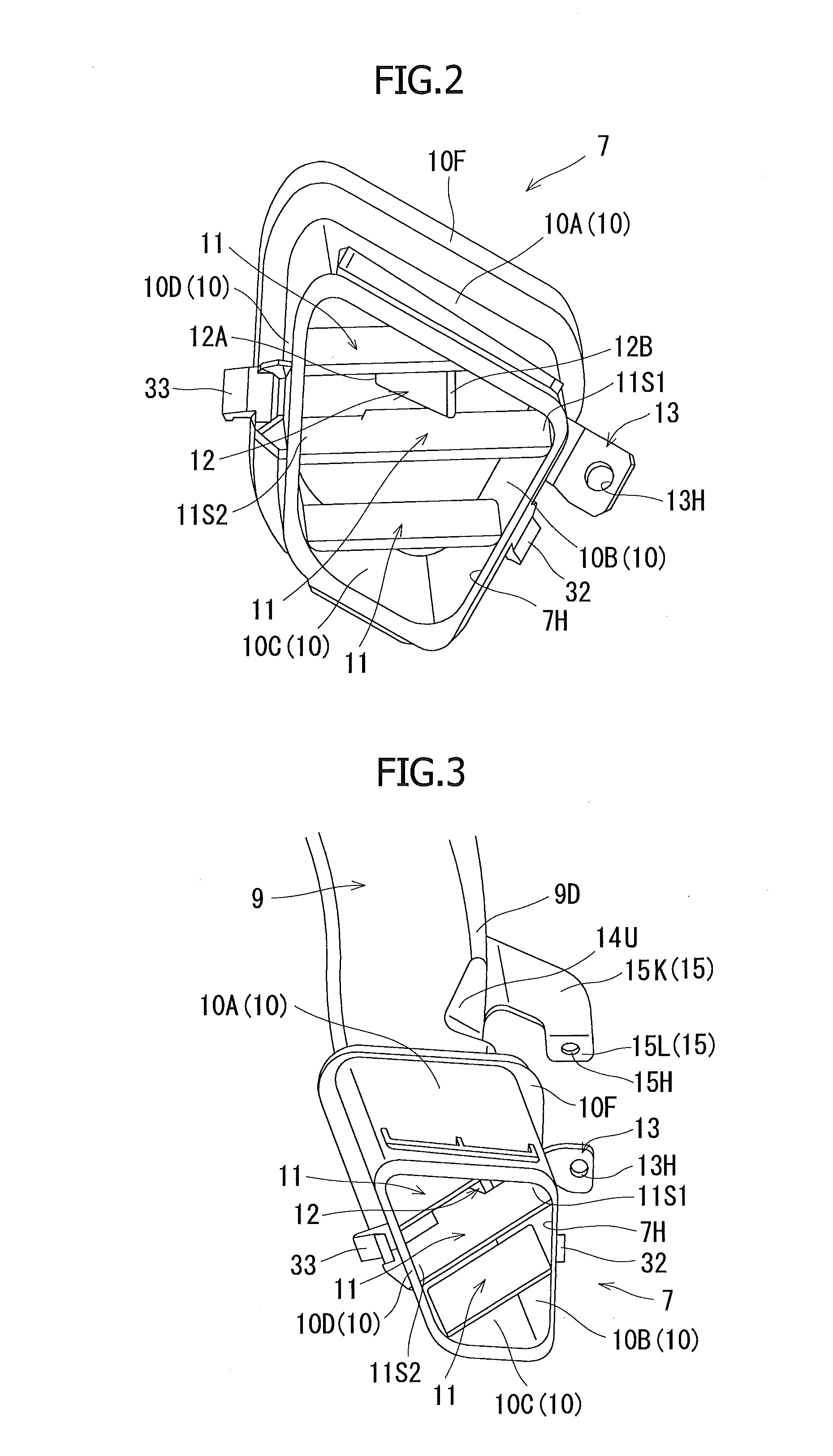
[0029]The fixing portion is disposed at the periphery of the convex portion of the air feed duct, so that the convex portion produces a bead effect for the fixing portion to thereby improve the rigidity of the fixing portion. This can improve the fixing strength of the fixing portion.
[0030]Hence, even if the air feed duct is easily bent and deformed, the air feed duct can improve the direction and the positional accuracy to the longitudinal fin. As a result, the turbulent flow impinging on the longitudinal fin can be correctly produced by the convex portion.
[0031]According to the present invention, it is possible to provide an air feed structure of a vehicle that can blow air in a plurality of directions but has fewer parts and has a smaller air blowing portion, and the air blowing portion can also be disposed in a narrow space.

Problems solved by technology

According to the structure in the related art, parts of fins and the like need to be disposed respectively at the upper air blowing port and the lower blowing port, so that the number of parts cannot be sufficiently decreased.
Furthermore, the air blowing portion is increased in size, which therefore makes it difficult to dispose the air blowing portion in a narrow space.

Method used


Image

  • Air feed structure for vehicle
  • Air feed structure for vehicle
  • Air feed structure for vehicle

Examples


Embodiment Construction

[0037]The present invention now will be described more fully hereinafter in which embodiments of the invention are provided with reference to the accompanying drawings. This invention may, however, be embodied in many different forms and should not be construed as limited to the embodiments set forth herein; rather, these embodiments are provided so that this disclosure will be thorough and complete, and will fully convey the scope of the invention to those skilled in the art.

[0038]The terminology used in the description of the invention herein is for the purpose of describing particular embodiments only and is not intended to be limiting of the invention. As used in the description of the invention and the appended claims, the singular forms “a”, “an” and “the” are intended to include the plural forms as well, unless the context clearly indicates otherwise. Unless otherwise defined, all technical and scientific terms used herein have the same meaning as commonly understood by one o...


PUM


Abstract

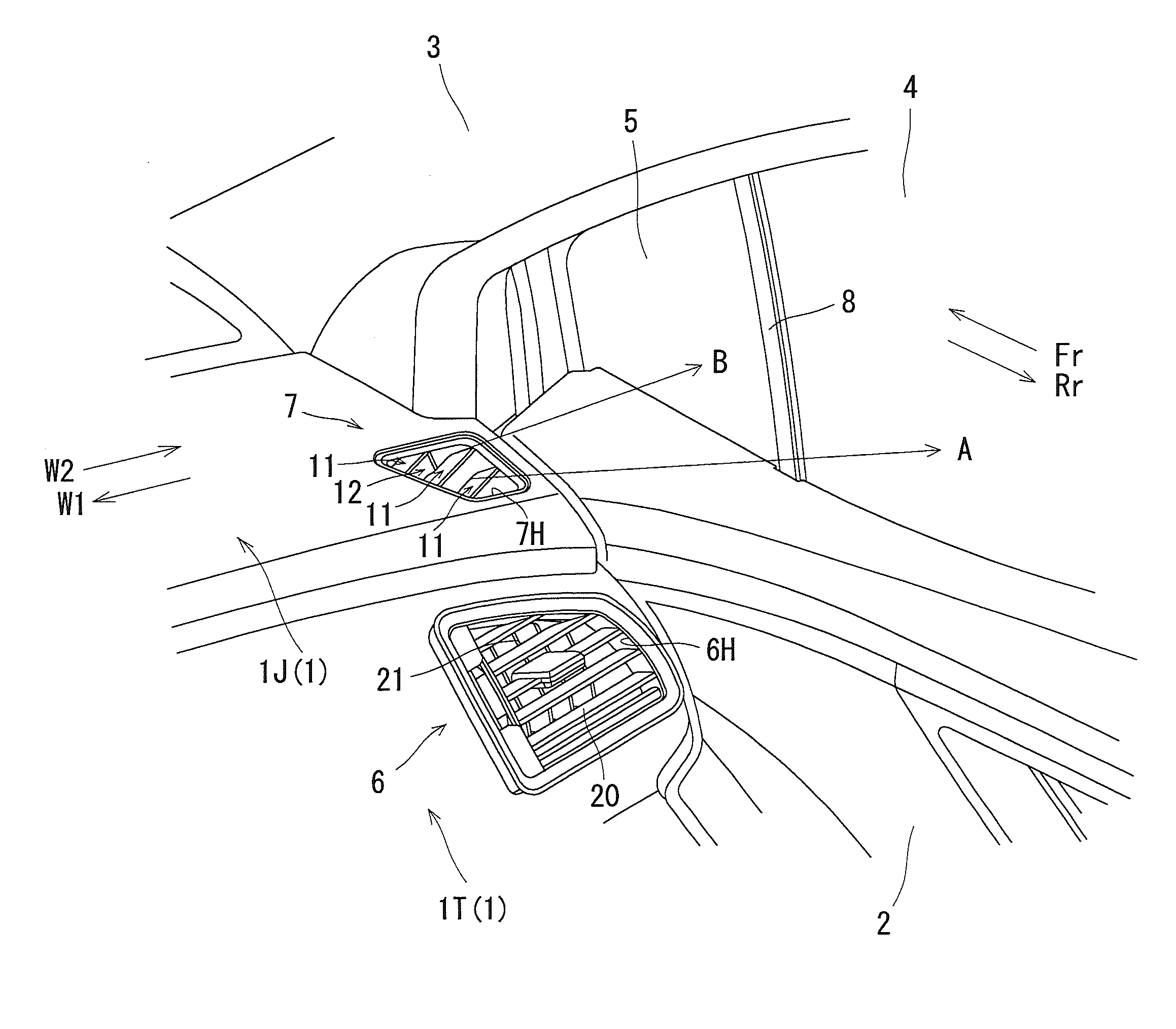
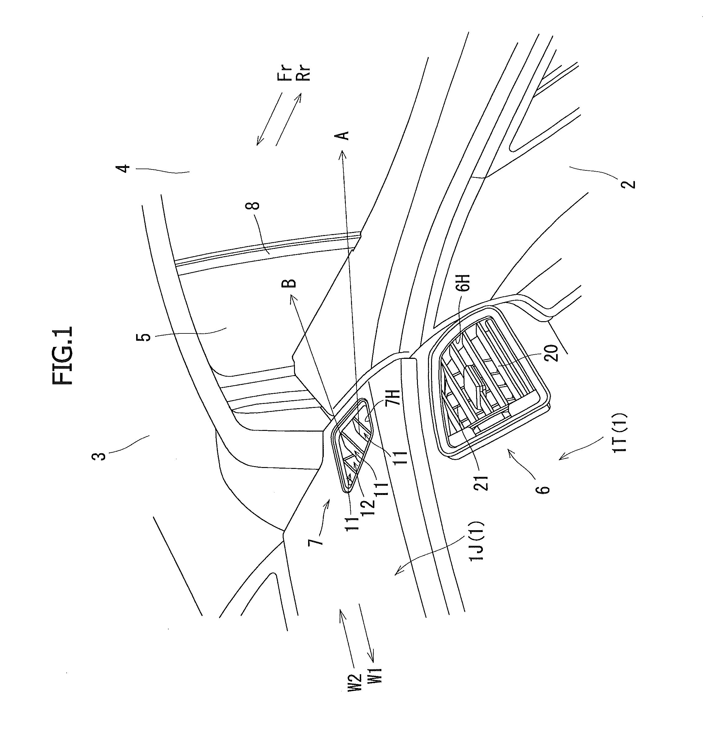
An air blowing portion 7 for blowing air flowing in an air feed duct 9 into a vehicle compartment is provided with a plurality of lateral fins 11, and the air blowing portion 7 is provided with a longitudinal fin 12, and the longitudinal fin 12 is inclined in such a way that as a portion is closer to a downstream side, the portion is positioned closer to a one side portion 11S1 side of the lateral fin 11, and a convex portion 14 protrudes into a flow passage of the air from a one side portion 9S1 side of the air feed duct 9 on an upstream side of the longitudinal fin 12.

Description

RELATED APPLICATION[0001]This application claims priority from Japanese Patent Application No. 2012-107267, filed May 9, 2012, the disclosure of which is incorporated by reference herein in its entirety.FIELD AND BACKGROUND OF THE INVENTION[0002]The present invention relates to an air feed structure of a vehicle in which an air blowing portion for blowing air flowing in an air feed duct into a vehicle compartment is provided with a plurality of lateral fins.[0003]An instrument panel has an air blowing portion of an air conditioner provided in a side portion thereof, the air blowing portion defogging a front window glass and a side window glass.[0004]In order to defog these window glasses, air must be blown in a plurality of directions to the front window glass and the side window glass from the air blowing portion.[0005]As a solution to this end, there is proposed a solution of providing a plurality of air blowing portions for blowing air in a plurality of directions respectively an...

Claims


Application Information

Patent Timeline
Patent Type & Authority Applications(United States)
IPC IPC(8): B60H1/34
CPCB60H1/34B60H1/3421
Inventor SEKI, KAZUHIKO
Owner SUZUKI MOTOR CORP
Why Eureka
Try Eureka