Torque Angle Sensor

a technology of torque sensor and torque angle, which is applied in the direction of instruments, galvano-magnetic hall-effect devices, force/torque/work measurement apparatus, etc., can solve the problem of voluminous sensors, reduce manufacturing costs, simplify assembly process, and reduce the height of torque sensors

Active Publication Date: 2013-11-21
LG INNOTEK CO LTD
View PDF5 Cites 20 Cited by
  • Summary
  • Abstract
  • Description
  • Claims
  • Application Information

AI Technical Summary

Benefits of technology

[0031]The torque angle sensor according to exemplary embodiments of the present disclosure has an advantageous effect in that a plurality of magnetic devices is packaged to be simplified into one magnetic device package to reduce the manufacturing cost and to simplify the assembly process by reducing the number of parts, whereby the product can be miniaturized by reduced height of a torque sensor.
[0032]Another advantageous effect is that the number of teeth in the main gear and sub gears forming the angle sensor unit is reduced to form gears with a smaller size than that of the conventional gears, and the main gear and the sub gears are arranged in mutual different housings to enable a miniaturization of the housing forming the angle sensor to the advantage of miniaturization of angle sensor.
[0033]Still another advantageous effect is that revolution of the sub gear is increased over that of the conventional sub gear to improve a self error ratio of a magnetic device relative to non-linearity accumulated per revolution of the sub gear over the conventional one.

Problems solved by technology

This configuration however suffers from a disadvantage in that the torque sensor becomes voluminous, and each magnetic device must be individually mounted on a printed circuit board.

Method used


Image

  • Torque Angle Sensor
  • Torque Angle Sensor
  • Torque Angle Sensor

Examples


Embodiment Construction

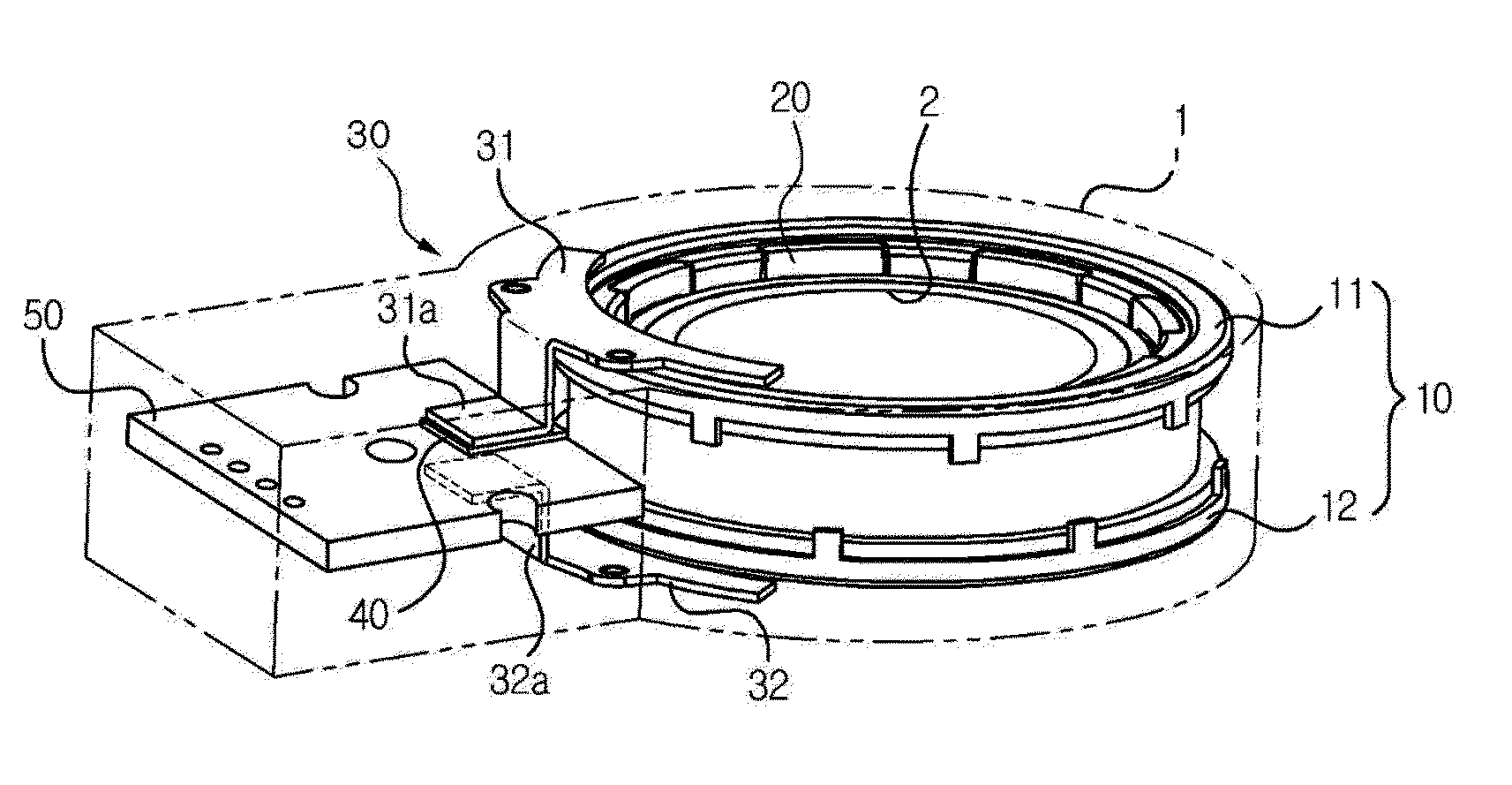
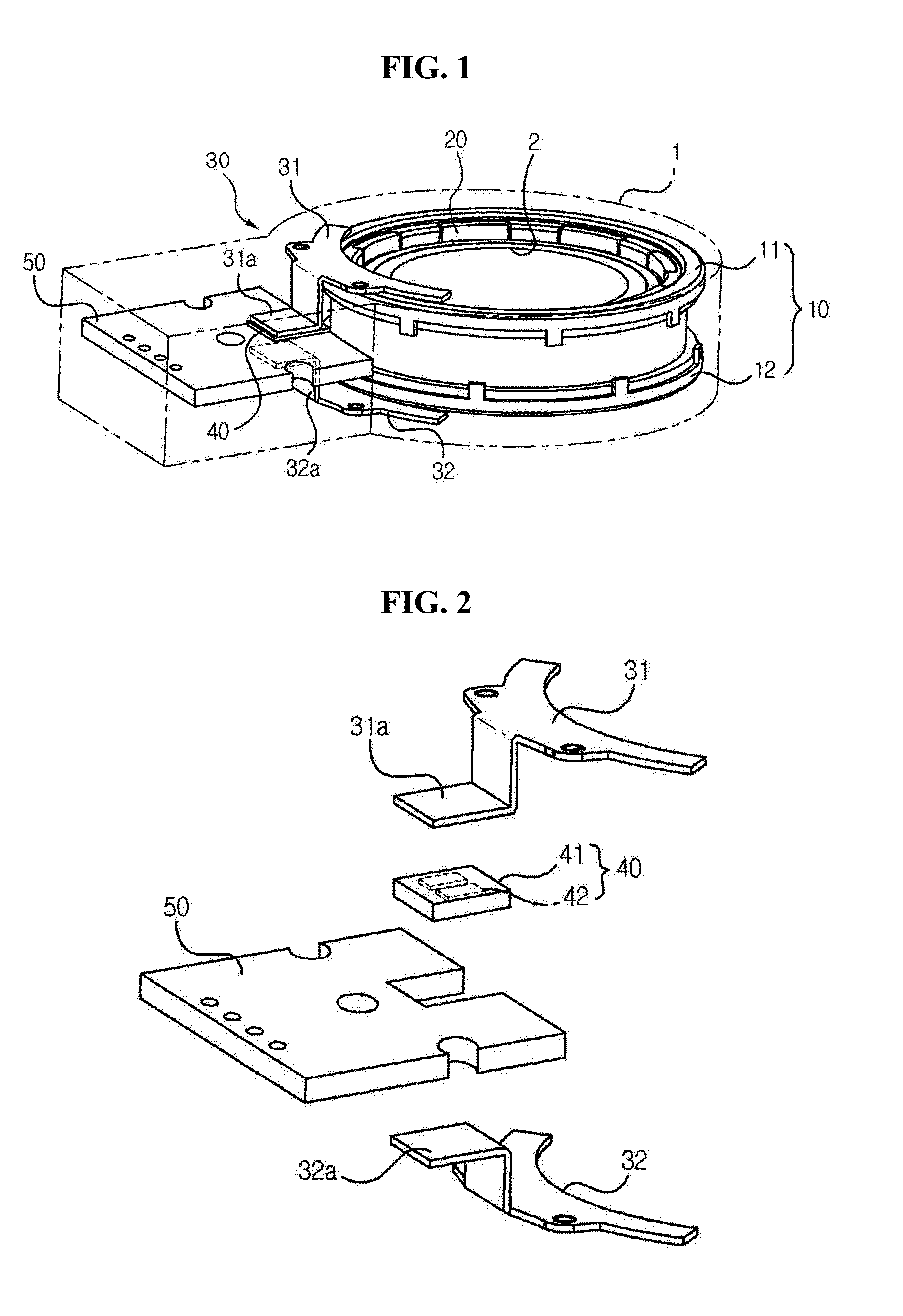
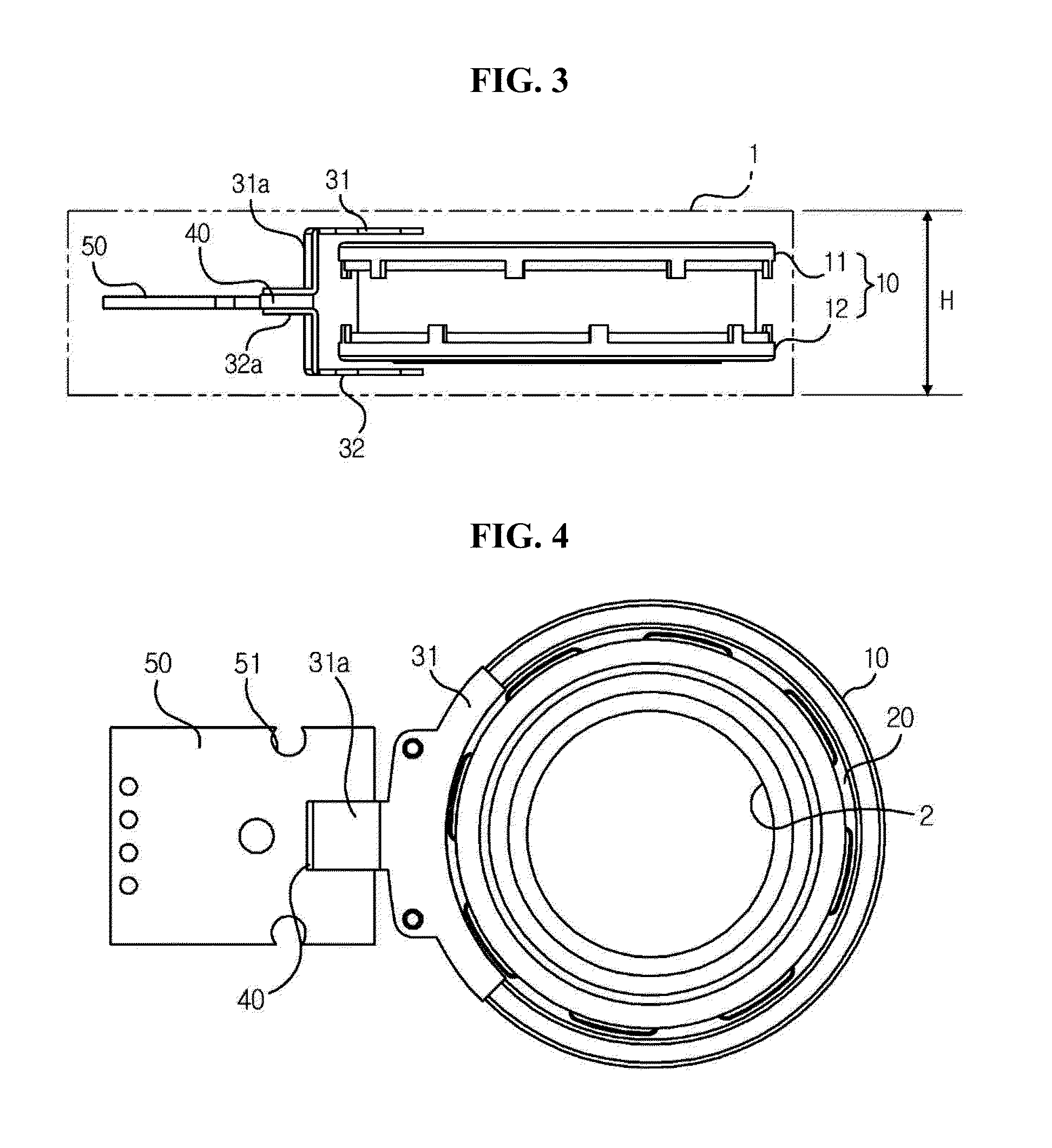
[0041]Advantages and features of the present invention may be understood more readily by reference to the following detailed description of exemplary embodiments and the accompanying drawings. Detailed descriptions of well-known functions, configurations or constructions are omitted for brevity and clarity so as not to obscure the description of the present disclosure with unnecessary detail. Thus, the present disclosure is not limited to the exemplary embodiments which will be described below, but may be implemented in other forms.

[0042]In the drawings, the width, length, thickness, etc. of components may be exaggerated or reduced for the sake of convenience. Furthermore, throughout the descriptions, the same reference numerals will be assigned to the same elements in the explanations of the figures, and explanations that duplicate one another will be omitted.

[0043]Accordingly, the meaning of specific terms or words used in the specification and claims should not be limited to the ...


PUM

PropertyMeasurementUnit
angle non-linearityaaaaaaaaaa
torqueaaaaaaaaaa
angleaaaaaaaaaa

Abstract

A torque angle sensor according to an exemplary embodiment of the present disclosure includes a torque sensor unit and an angle sensor unit at a housing centrally arranged with a rotation shaft, the torque sensor unit including a stator installed inside the housing, a torque magnet rotatably installed at a center of the stator in conjunction with rotary operation of the rotation shaft, a collector installed at the housing to transmit a magnetic field of the torque magnet, a magnetic device module formed with an individually operating first magnetic device and a second magnetic device in one package to detect the magnetic field transmitted by the collector, and a PCB (Printed Circuit Board) mounted with the magnetic device module, wherein the PCB is arranged to a direction perpendicular to an axial direction of the rotation shaft and installed at a distal end with the magnetic device module.

Description

CROSS-REFERENCE TO RELATED APPLICATIONS[0001]This application claims the benefit under 35 U.S.C. §119 of Korean Application Nos. 10-2012-0052340, filed May 17, 2012, and 10-2012-0060437, filed Jun. 5, 2012, which are hereby incorporated by reference in their entirety.BACKGROUND OF THE DISCLOSURE[0002]1. Field of the Invention[0003]The teachings in accordance with exemplary and non-limiting embodiments of this disclosure relate generally to a torque sensor mounted on a vehicle to detect a torque change between an input shaft and an output shaft, and to a torque angle sensor configured to measure changes in rotation angle between an input shaft and an output shaft.[0004]2. Discussion of the Related Art[0005]Generally, almost every vehicle employs an electric power-assist steering system. That is, a steering system that assists a steering force of a vehicle with a separate power is used to enhance the motion stability of a vehicle.[0006]Conventionally, the auxiliary steering device use...

Claims


Application Information

Patent Timeline
Patent Type & Authority Applications(United States)
IPC IPC(8): G01L3/10G01B7/30
CPCG01L3/104G01B7/30G01L3/101G01L5/221B62D6/10B62D15/0215G01L3/10
Inventor LEE, CHANG HWANLEE, YOUNG WUKWOO, MYUNG CHUL
Owner LG INNOTEK CO LTD
Why Eureka
Try Eureka