Cooling air intake device for vehicle

Inactive Publication Date: 2013-11-21
KYMCO
View PDF9 Cites 3 Cited by
  • Summary
  • Abstract
  • Description
  • Claims
  • Application Information

AI Technical Summary

Benefits of technology

[0007]The efficacy that the present invention can provide by means of the above technical solution is that by providing a cooling air intake device with a first intake compartment and a second intake compartment, heat dissipation and cooling can be performed simultaneously on at least two components/sub-assemblies of a vehicle so as to enhance the operation performance of the cooling air intake device.
[0008]Another object of the present invention is to provide a cooling air intake device of vehicle the, wherein by providing a blocking section along a circumferential flange of a base plate of the cooling air intake device, when viewed in a direction from the rear side of the vehicle toward the head side, the cooli

Problems solved by technology

This imposes extreme limitation to the operation

Method used


Image

  • Cooling air intake device for vehicle
  • Cooling air intake device for vehicle
  • Cooling air intake device for vehicle

Examples


Example

[0018]The following descriptions are exemplary embodiments only, and are not intended to limit the scope, applicability or configuration of the invention in any way. Rather, the following description provides a convenient illustration for implementing exemplary embodiments of the invention. Various changes to the described embodiments may be made in the function and arrangement of the elements described without departing from the scope of the invention as set forth in the appended claims.

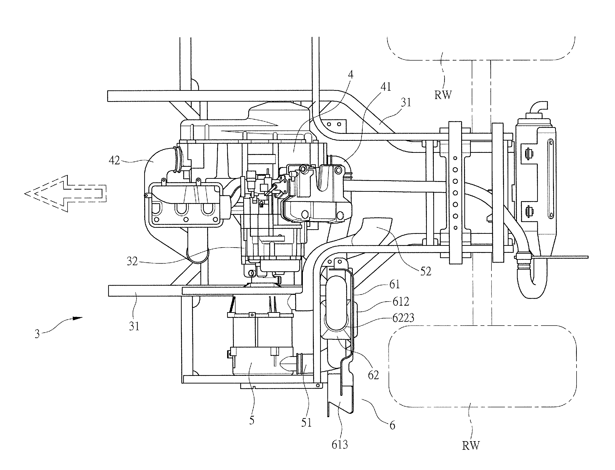
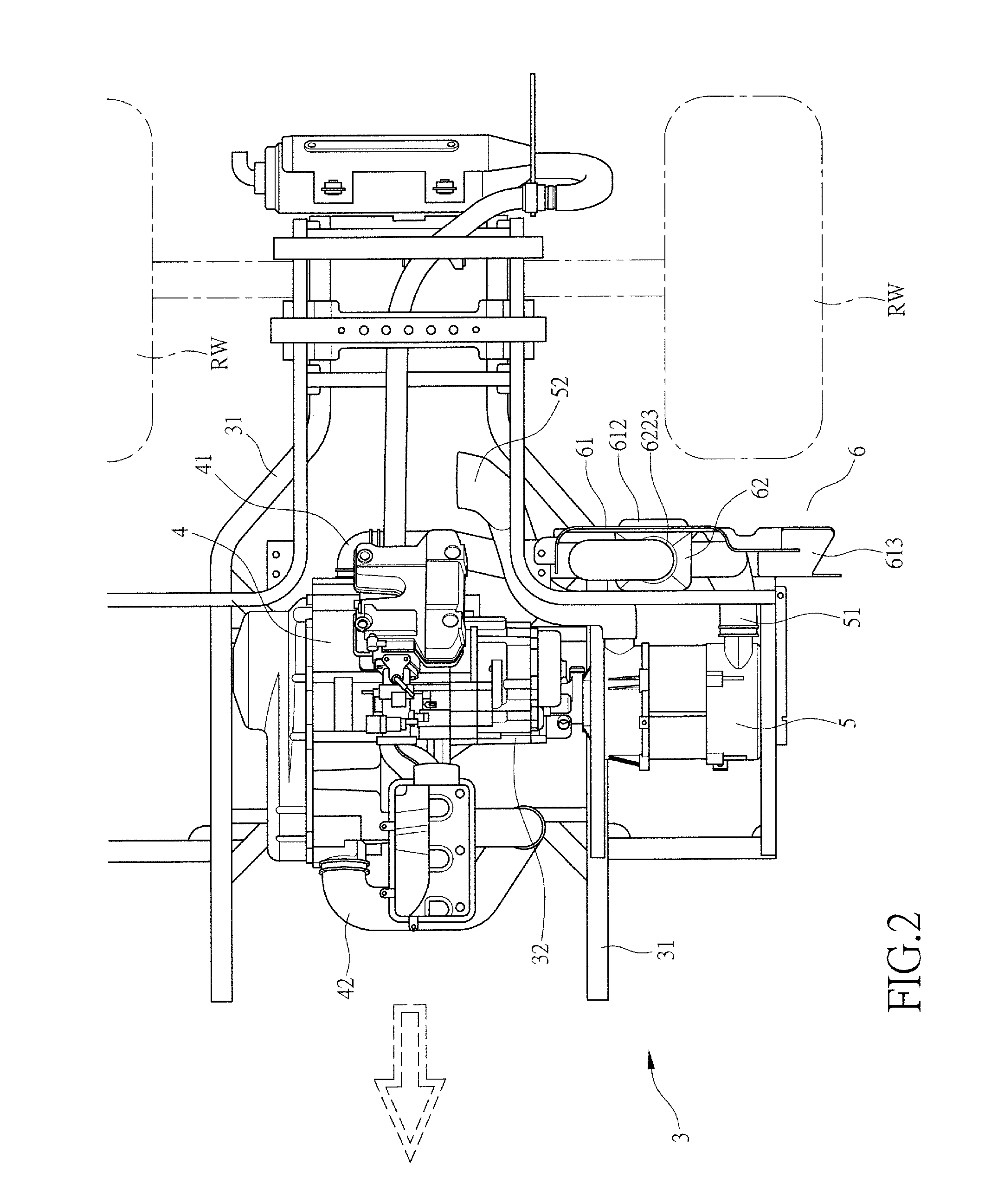
[0019]Referring first to FIG. 2, in which the arrow indicates the head direction of a vehicle 3, the vehicle 3 according to the present invention comprises a frame 31 on which an engine 32 is mounted. The engine 32 is provided with a transmission 4. The transmission 4 comprises therein a continuous variable transmission system (not shown). Further, the frame 31 is provided with a generator 5 located beside the engine 32. The generator 5 is driven by the engine 32.

[0020]The transmission 4 is provided...


PUM


Abstract

A cooling air intake device is mounted to a frame of a vehicle and includes a base plate and an intake box. The intake box is mounted on the base plate that includes a first admission section and a blocking section adjacent to the first admission section. The intake box includes a first intake compartment and a second intake compartment. The first intake compartment corresponds to the first admission section of the base plate. The first intake compartment includes a first baffle plate mounted therein. The first intake compartment has a side wall in which a first discharge section is formed. The second intake compartment is arranged above the first intake compartment in such a way that a second baffle plate is arranged between the first intake compartment and the second intake compartment. The second intake compartment includes a second admission section and a second discharge section.

Description

TECHNICAL FIELD OF THE INVENTION[0001]The present invention generally relates to a cooling air intake device for vehicle, and more particularly to a structure of cooling air intake device that enhances the operation performance of the cooling air intake device.DESCRIPTION OF THE PRIOR ART[0002]A conventional vehicle 1, as shown in FIG. 1, comprises a frame 11 on which an engine 12 is suspended. The engine 12 is provided with a transmission 2 adjacent thereto. The transmission 2 comprises a continuous variable transmission system (not shown) arranged therein.[0003]The transmission 2 comprises an air ingress conduit 21 for drawing in cooling air and an air egress conduit 22. External air that is used to cool the continuous variable transmission system of the transmission 2 flows through the air ingress conduit 21 into the transmission 2 to cool the components / parts of the continuous variable transmission system. The air that is heated in this process is discharged to the outside throu...

Claims


Application Information

Patent Timeline
IPC IPC(8): F01P1/08
CPCF01P1/08B60K11/06F01P2001/005
Inventor WANG, JUN-KAISU, WEN-MINGCHANG, CHI-HAN
Owner KYMCO
Why Eureka
Try Eureka