Mobile terminal, power transfer system and computer-readable storage medium

a technology of power transfer system and mobile terminal, which is applied in the direction of power management, wireless communication, power supply for data processing, etc., can solve the problems of unsuitable wireless power transfer system, unsuitable for mobile terminal use during motion, and battery powering cellular phones may run out unexpectedly, so as to achieve efficient power transfer

Inactive Publication Date: 2013-11-21
EMPIRE TECH DEV LLC
View PDF7 Cites 5 Cited by
  • Summary
  • Abstract
  • Description
  • Claims
  • Application Information

AI Technical Summary

Benefits of technology

[0008]One aspect of the embodiment may provide a technology for realizing an efficient power transfer even during motion of a mobile terminal.

Problems solved by technology

However, cellular phones, such as smart-phones, may have a relatively large number of functions, and a battery powering the cellular phones may run out unexpectedly when various functions are utilized for a relatively long period of time, for example.
However, since the charging of the battery does not occur unless the mobile terminal is placed close to the charging unit, this wireless power transfer may be unsuited for use during motion of the mobile terminal.
However, since the coil size needs to be increased in order to extend the power transfer distance, this first wireless power transfer system may be unsuited for implementation in portable devices, such as mobile terminals.
In addition, in order to realize an efficient power transfer, a power transmitter in a transmitting end and a power receiver in the receiving end device may need to be oriented to oppose each other, which may limit the arrangement of the power transmitter, for example.
Furthermore, the need to orient the power transmitter and the power receiver to oppose each other may make it difficult to transfer the power according to this first wireless power transfer system during motion of the mobile terminal.
However, according to this second wireless power transfer system, the power transfer efficiency may be considerably reduced compared to that of the first wireless power transfer system unless the beam width of either a transmitting antenna or a receiving antenna is narrowed.
But narrowing the beam width of the transmitting or receiving antenna may make it more difficult for the mobile terminal to receive the microwaves during motion.
Moreover, according to the first and second wireless power transfer systems, the cost of setting up the power transmitters in an environment in which the mobile terminal is used may become considerably high when a relatively large number of power transmitters are to be set up in the environment.

Method used


Image

  • Mobile terminal, power transfer system and computer-readable storage medium
  • Mobile terminal, power transfer system and computer-readable storage medium
  • Mobile terminal, power transfer system and computer-readable storage medium

Examples


first embodiment

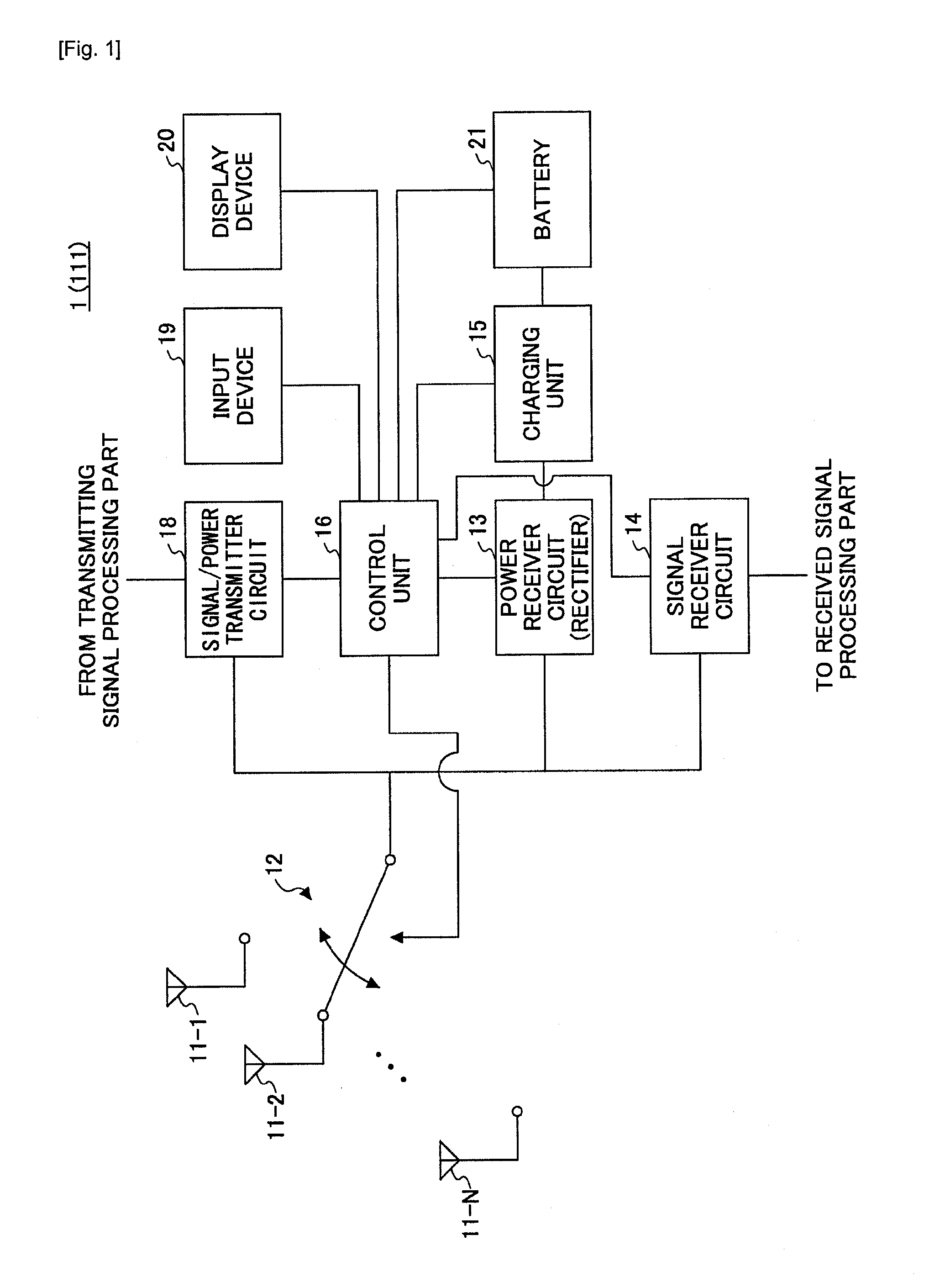
[0024]FIG. 1 is a block diagram illustrating an example of a mobile terminal in a first embodiment. In one example, a mobile terminal 1 illustrated in FIG. 1 may be formed by a cellular phone, for example, but the mobile terminal 1 may be formed by any suitable device that includes a plurality of antennas to receive radio waves, a receiver circuit to receive power of the radio waves received by the plurality of antennas using a diversity technique, and a charging unit to charge a rechargeable battery coupled to the device by the power of the radio waves received by the receiver circuit. In the case of the cellular phone, a speaker and a microphone (both not illustrated) may be provided to enable a telephone conversation with another party.

[0025]The mobile terminal 1 illustrated in FIG. 1 may include a plurality of antennas 11-1 through 11-N (N is a natural number greater than 1), a switching circuit 12, a power receiver circuit 13, a signal receiver circuit 14, a charging unit 15, a...

second embodiment

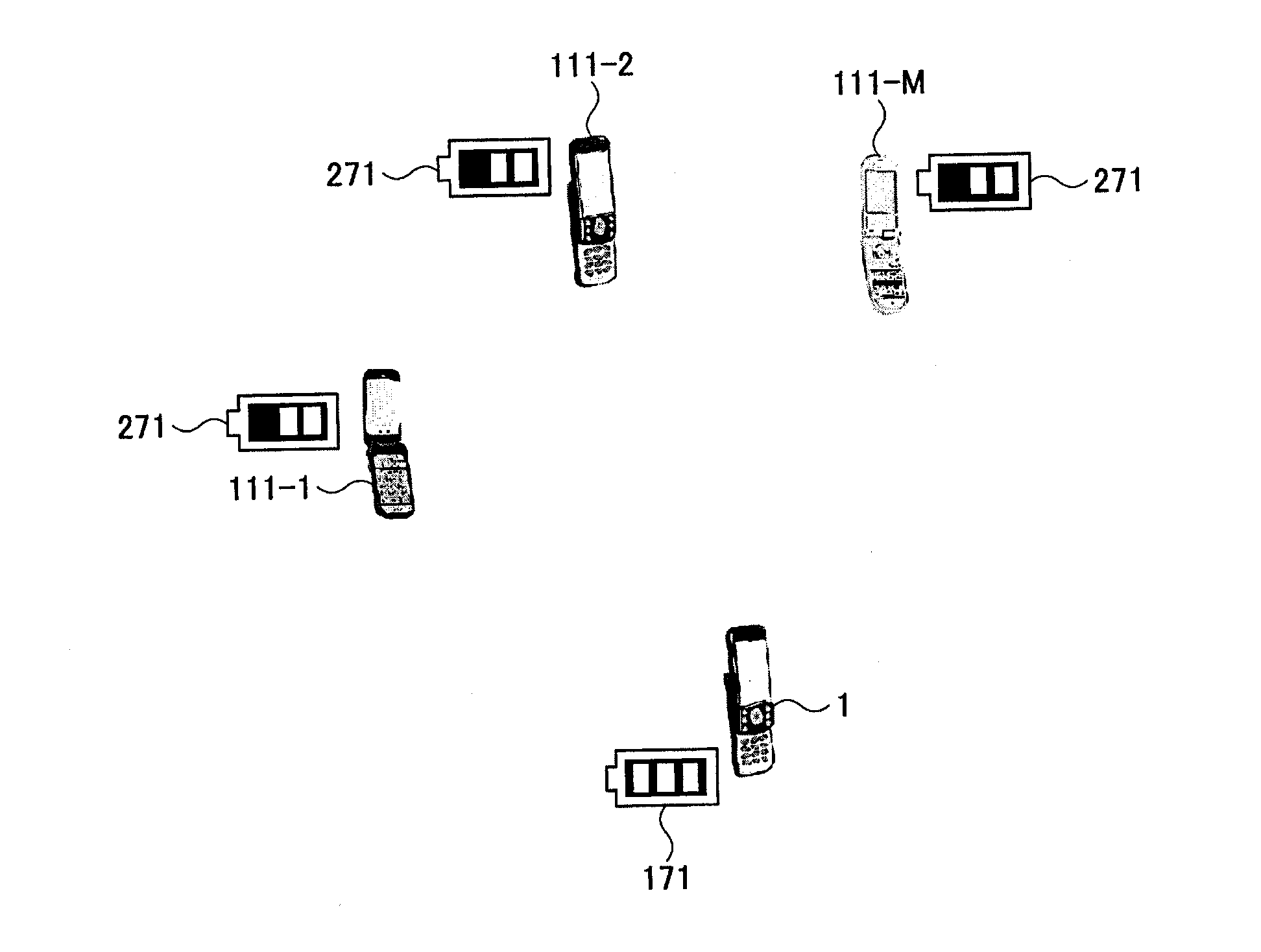
[0054]FIG. 6 is a flow chart for explaining an example of a process performed by a power transfer system in a second embodiment. FIG. 7 is a diagram for explaining an example of a power transfer in the second embodiment, and FIG. 8 is a diagram for explaining an example of a state after the power transfer in the second embodiment. In FIGS. 7 and 8, it may be assumed for the sake of convenience that each of a power receiving mobile terminal 1 and power transmitting mobile terminals 111-1 through 111-M (M is a natural number greater than 1) has the structure illustrated in FIG. 1 or FIG. 2, and the power transmitting mobile terminals 111-1 through 111-M are located within a communicatable range from the power receiving mobile terminal 1. Further, it may be assumed for the sake of convenience that a battery fuel gauge 271 is displayed on the display device 20 of each of the mobile terminals 1 and 111-1 through 111-M.

[0055]In FIG. 6, steps S11 through S17 may be executed by the control ...


PUM


Abstract

A mobile terminal may include a plurality of antennas to receive radio waves, a receiver circuit to receive power of the radio waves received by the plurality of antennas using a diversity technique, and a charging unit to charge a rechargeable battery coupled to the mobile terminal by the power of the radio waves received by the receiver circuit.

Description

TECHNICAL FIELD[0001]The present disclosure relates to a mobile terminal, a power transfer system, and a computer-readable storage medium.BACKGROUND ART[0002]Mobile terminals, such as cellular phones, are useful communication tools. However, cellular phones, such as smart-phones, may have a relatively large number of functions, and a battery powering the cellular phones may run out unexpectedly when various functions are utilized for a relatively long period of time, for example. When the battery runs out, the functions of the cellular phones may not be used unless the battery is replaced or the cellular phone is directly connected to a power supply.[0003]Recently, there is active research and development in wireless power transfer. The wireless power transfer is also sometimes referred to as contactless power transfer. For example, by using the wireless power transfer, it may be possible to charge a battery of a mobile terminal, such as cellular phone, by merely placing the mobile ...

Claims


Application Information

Patent Timeline
Patent Type & Authority Applications(United States)
IPC IPC(8): H04W52/00
CPCH04W52/00G06F1/26H04B5/0037H04B7/0805H04B7/0848H02J50/20H02J50/80H02J7/342H02J50/402H04B7/0837H02J2310/22
Inventor OHIRA, MASATAKAKONO, MICHIYO
Owner EMPIRE TECH DEV LLC
Why Eureka
Try Eureka