Split-phase high-efficiency reactive enhanced active transducer

a transducer and reactive technology, applied in the field of wireless energy harvesting devices, can solve the problems of ac-dc conversion, need for more complex rectifiers, and difficulty in designing a compact transducer comprised of relatively few and light components, and achieves the effect of smooth voltage output and increasing performan

Active Publication Date: 2018-05-03
NEWMAN JOSHUA HERSHEL
View PDF8 Cites 2 Cited by
  • Summary
  • Abstract
  • Description
  • Claims
  • Application Information

AI Technical Summary

Benefits of technology

[0036]c) the flyback effect resulted from the split phase configuration is prevented;
[0037]d) smooth voltage output suitable for mobile devices;
[0038]e) high-efficiency MSRC for transforming, amplifying and regulating the AC

Problems solved by technology

Nevertheless, where a significantly more potent antenna such as a split phase flattened-torus antenna is used, there is a need for more complex rectifiers that as unneeded by-product often have larger dimensions due to increased usage of durable components.
Designing a compact transducer comprised of relatively few and light components for converting tens of volts AC to the 5V DC voltage and one-hundred or more milliamps that is suitable for charging mobile devices such as phones and tablets, is not an easy task.
A person

Method used


Image

  • Split-phase high-efficiency reactive enhanced active transducer
  • Split-phase high-efficiency reactive enhanced active transducer
  • Split-phase high-efficiency reactive enhanced active transducer

Examples


Embodiment Construction

[0045]The present invention will be understood from the following detailed description of preferred embodiments, which are meant to be descriptive and not limiting. For the sake of brevity, some well-known features, methods, systems, procedures, components, circuits, and so on, are not described in detail.

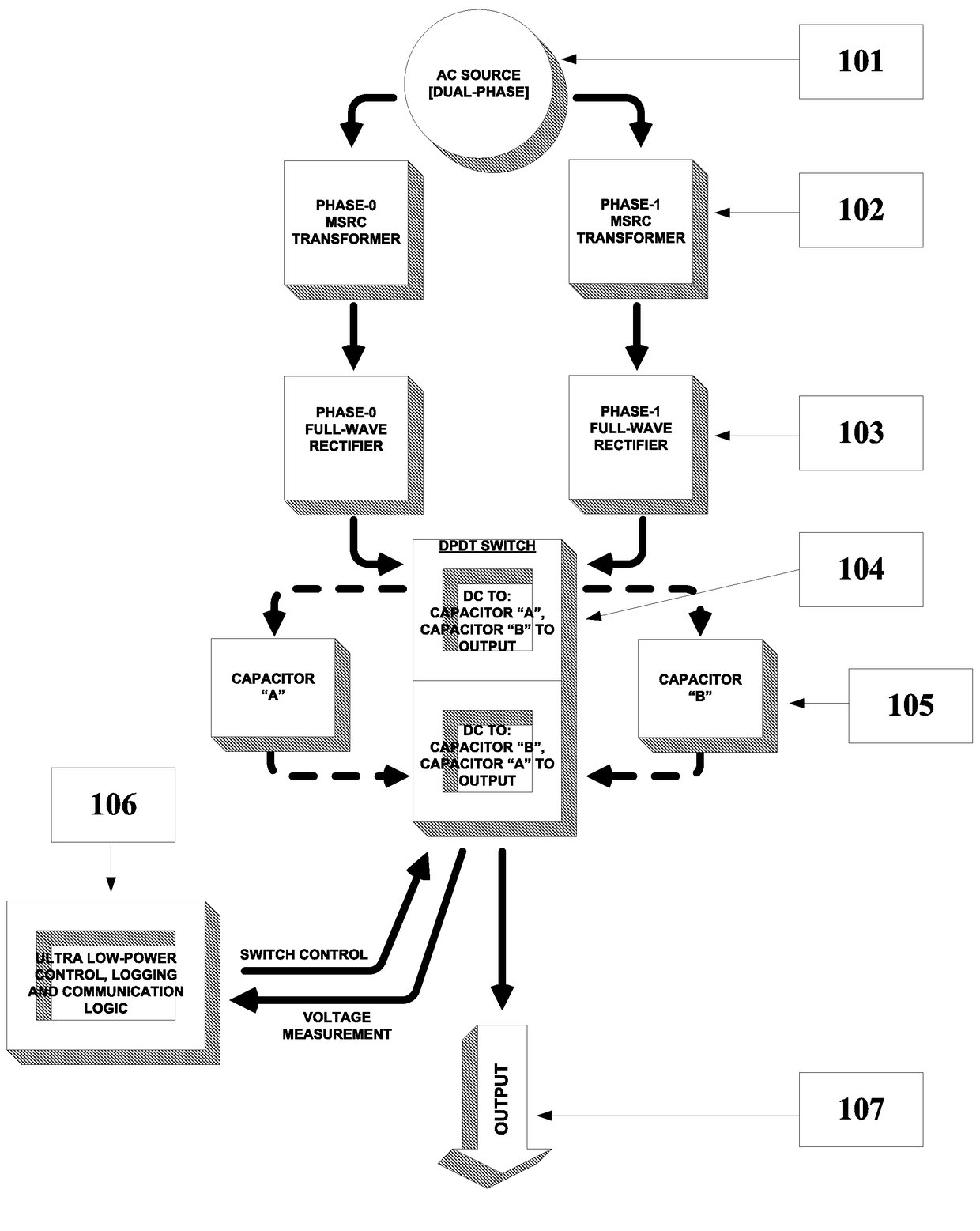
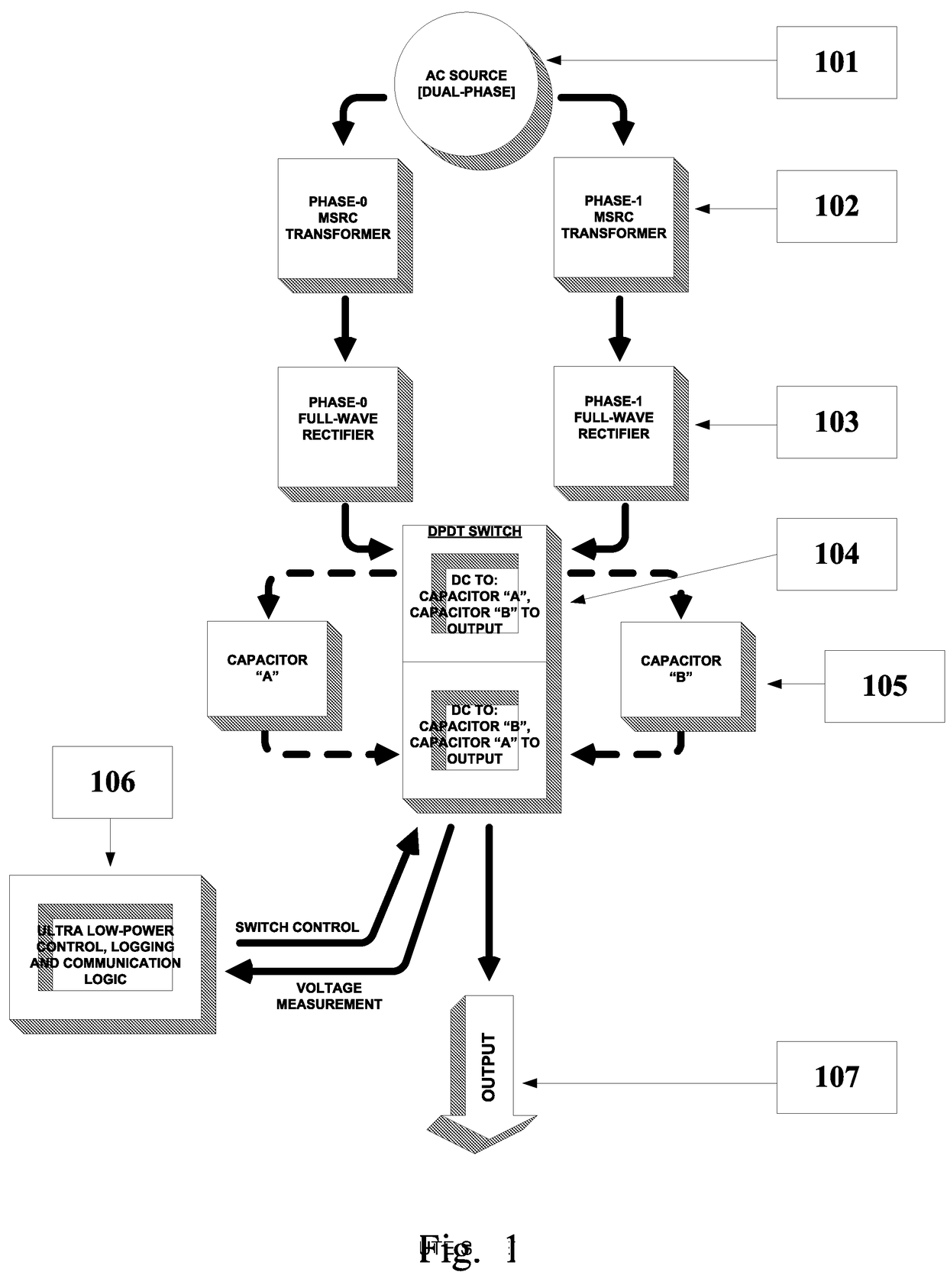
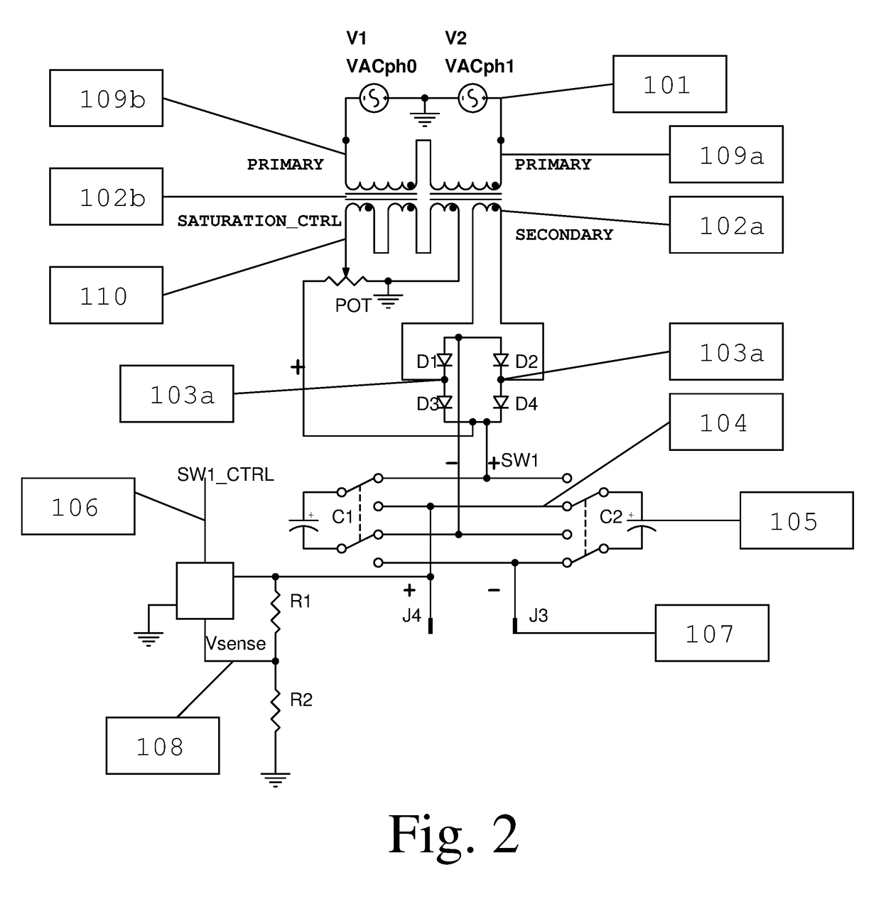
[0046]As seen in FIG. 1, the energy harvesting circuit starts with an AC source such as a split phase antenna [101]. The next stages consist of two parallel paths, each comprising a transformer [102], and a full wave rectifier [103].

[0047]An ultra-low-power microcontroller [106] operates a double-position double-throw switch [104], which switches the capacitors [105] from charging from the input, to providing energy to the output [107].

[0048]The use of two parallel paths allows for several improvements over the prior art. First of all, the energy is harvested at both positive and negative points of the waveform, at a given time; the inputs are located at points of the antenna that ...


PUM


Abstract

An energy harvesting circuit is provided that consists of two parallel paths, each comprising a transformer, full wave rectifier, and capacitor. An ultra-low-power microcontroller operates a double-position double-throw switch, which switches the capacitors from charging from the input, to providing energy to the output.

Description

FIELD OF THE INVENTION[0001]The present invention relates generally to the field of wireless energy harvesting devices. More specifically, relates to the field of split-phased AC-DC transducer devices for energy harvesting by split phased antennas.BACKGROUND OF THE INVENTION[0002]The increasing crowding of the electromagnetic spectrum as well as increased power demands of mobile devices both spur interest in wireless energy harvesting.[0003]Typical energy harvesting devices are comprised of an antenna which induces AC current from gathered ambient EM radiation, and an AC-DC converter which converts the AC current to usable DC current. Simple energy harvesting devices have a simple rectifier and an antenna; combined, the devices are called rectennas (rectifier-antenna).[0004]While dealing with low voltage values that are induced from a typical dipole antenna, a simple diode, is often sufficient for a safely operational harvesting device. Nevertheless, where a significantly more poten...

Claims


Application Information

Patent Timeline
IPC IPC(8): H02J50/10H04B5/00H02M7/06H02M7/08H02M7/217
CPCH02J50/10H04B5/0037H04B5/0087H02M7/064H02M7/08H02M7/2173H02J50/001H02J50/00
Inventor NEWMAN, JOSHUA HERSHEL
Owner NEWMAN JOSHUA HERSHEL
Why Eureka
Try Eureka