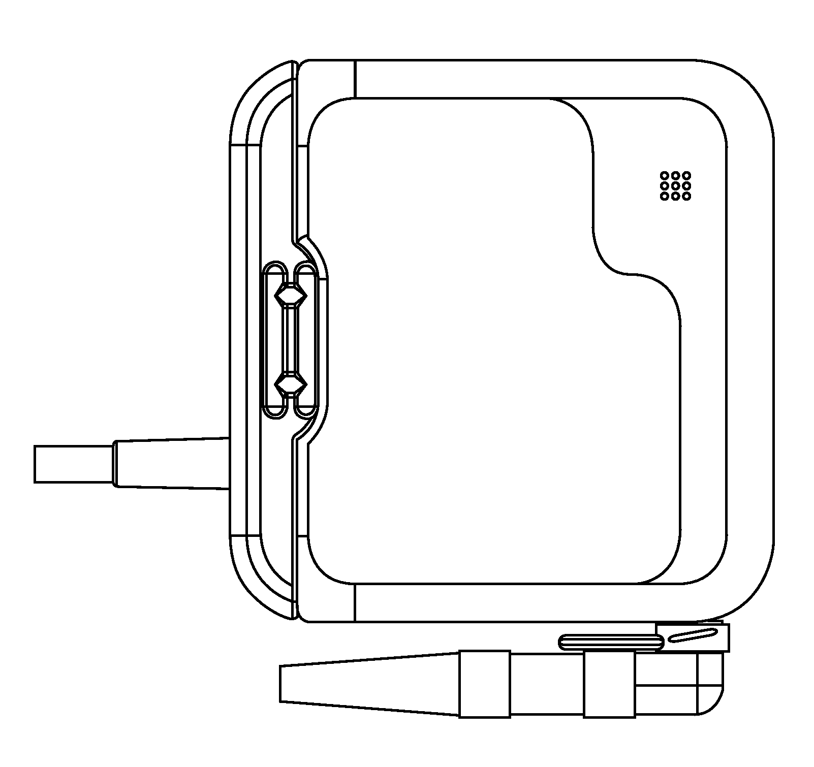
Touch screen interface and infrared communication system integrated into a battery
a touch screen interface and infrared communication technology, applied in the field of external batteries, can solve the problems of increased risk of trauma to the exit site, cumbersome carrying and managing of peripheral devices, and increased risk of injury to the exit si
- Summary
- Abstract
- Description
- Claims
- Application Information
AI Technical Summary
Benefits of technology
Problems solved by technology
Method used
Image

Examples
Embodiment Construction
[0055]Various embodiments and aspects of the invention(s) will be described with reference to details discussed below, and the accompanying drawings will illustrate the various embodiments. The following description and drawings are illustrative of the invention and are not to be construed as limiting the invention. The term “coupled” as used herein, may mean directly coupled or indirectly coupled through one or more intervening components. Numerous specific details are described to provide a thorough understanding of various embodiments of the present invention. However, in certain instances, well-known or conventional details are not described in order to provide a concise discussion of embodiments of the present inventions.
Overview
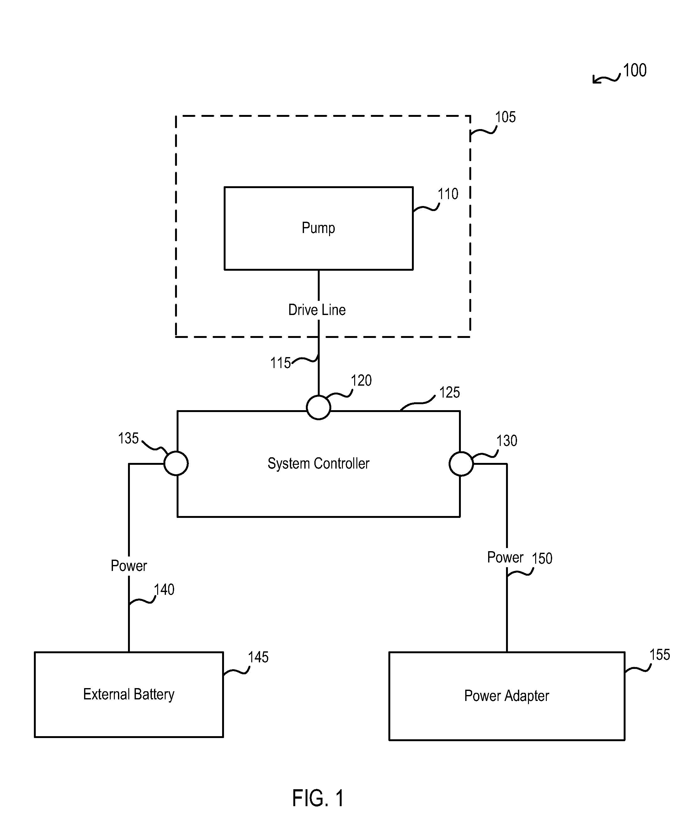
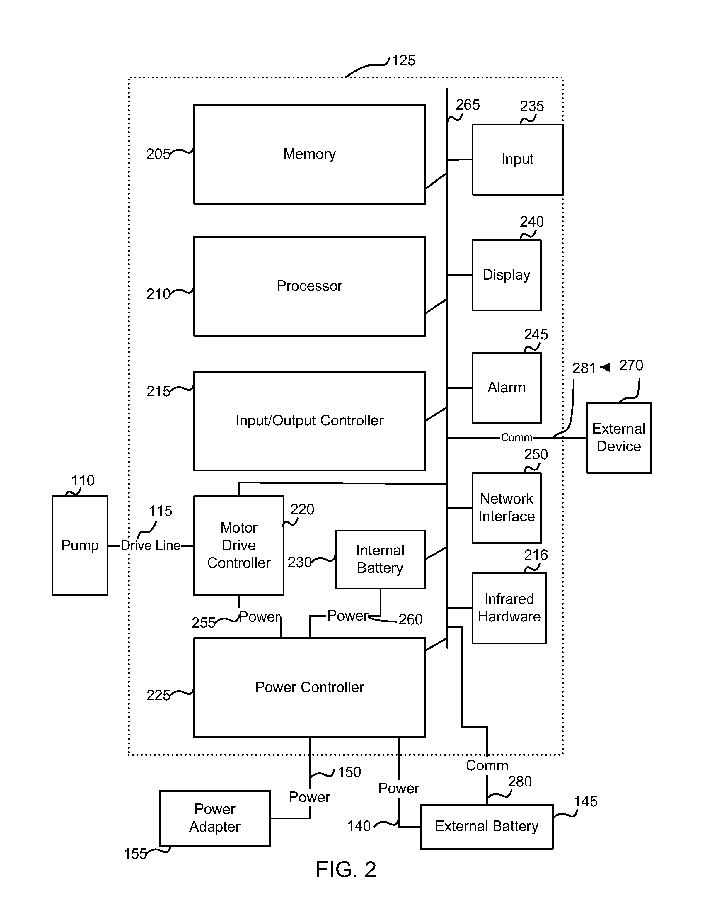
[0056]Throughout the description, the methods, apparatuses, and systems of the present invention are discussed in the context of a ventricular assist system (VAS, such as a left ventricular assist device (LVAD)). It will be appreciated, however, that th...
PUM
 Abstract
Description
Claims
Application Information
 - R&D Engineer
- R&D Manager
- IP Professional
- Industry Leading Data Capabilities
- Powerful AI technology
- Patent DNA Extraction
Browse by: Latest US Patents, China's latest patents, Technical Efficacy Thesaurus, Application Domain, Technology Topic.
© 2024 PatSnap. All rights reserved.Legal|Privacy policy|Modern Slavery Act Transparency Statement|Sitemap