

Vehicle upper structure
a technology for vehicles and structures, applied in the direction of superstructure sub-units, roofs, vehicle components, etc., can solve the problems of increasing the bending moment, and affecting the weight reduction
- Summary
- Abstract
- Description
- Claims
- Application Information
AI Technical Summary
Benefits of technology
Problems solved by technology
Method used
Image

Examples
Embodiment Construction
[0025]One embodiment of the present invention will now be specifically described based on the drawings.
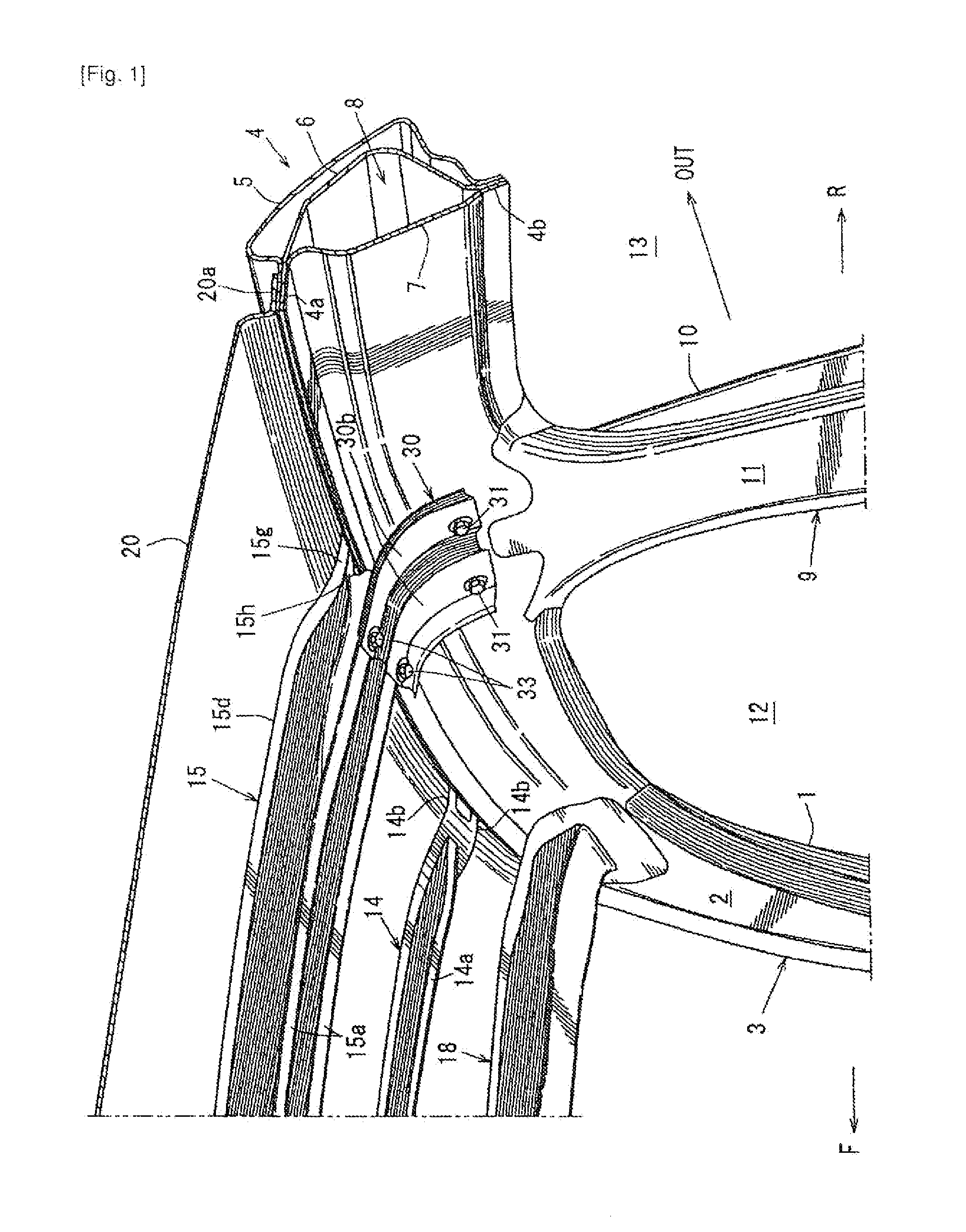
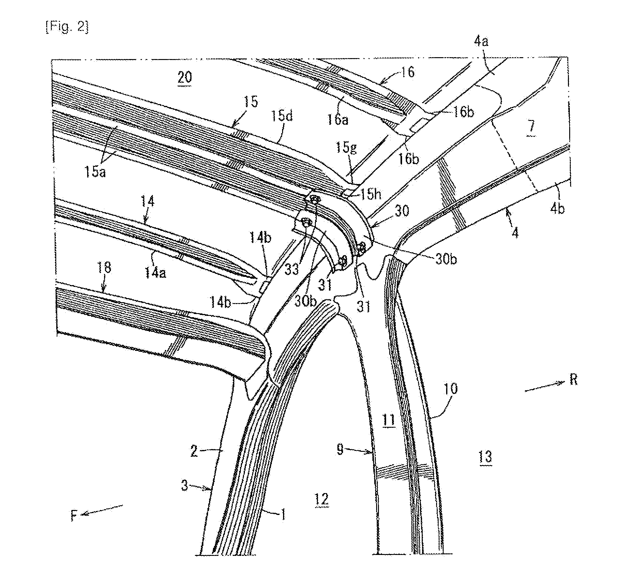
The drawings illustrates a vehicle upper structure, wherein FIG. 1, FIG. 2 and FIG. 3 are, respectively, a perspective view as viewed upwardly toward a roof from a bottom of a vehicle, a perspective view as viewed from an angle different from that in FIG. 1, and a rear view of the vehicle upper structure, which cross-sectionally represents a roof side rail member.
In FIGS. 1 and 2, a front pillar outer panel 1 and a front pillar inner panel 2 are joined and fixed together to provide a front pillar 3 having a closed cross-section extending obliquely upwardly toward a rear of the vehicle.
A roof side rail 4 as a roof side rail member is provided at a rear end of the front pillar 3 to extend continuously from the front pillar 3 toward the rear of the vehicle.
The roof side rail 4 is a rigid vehicle body member extending along a vehicle front-rear direction in an upper and side region (i....
PUM
 Abstract
Description
Claims
Application Information