Illuminated keyboard

Inactive Publication Date: 2013-12-05
ZIPPY TECH
View PDF3 Cites 12 Cited by
  • Summary
  • Abstract
  • Description
  • Claims
  • Application Information

AI Technical Summary

Benefits of technology

The invention is a new way to make a keyboard that is thinner and more uniform in its lighting. By positioning a light source substrate between key clusters, the need for a thick light guide plate covering the entire keyboard is eliminated. This allows for a thinner, more cost-efficient keyboard design. Additionally, the invention includes a light transmission channel that contains at least one LED, which can generate more uniform lighting compared to conventional techniques. Overall, the invention provides a thinner, more cost-efficient, and more uniform keyboard design.

Problems solved by technology

As the situations of using the computer are diversified these days, in a low luminosity or dim environment without sufficient illumination people cannot make accurate keystrokes to output data correctly.
As the illuminated keyboards are mostly used in a low luminosity or dim environment, uniform illumination of the entire keyboard often results in too strong of luminosity to create annoyance to other people in the neighborhood.
Moreover, in the low luminosity environment, people's visual sensitivity to objects is lower, light projection of the entire keyboard makes users difficult to identify each keycap.
Moreover, light emitted from two neighboring keycaps tends to generate interference and not easy to distinguish.
The light guide plate is formed at a substantial thickness and makes shrinking the illuminated keyboard difficult.
As a result, it is difficult to be adopted on the ultrabooks, and the cost of the illuminated keyboard also is higher.
Such a concern creates a lot of constraints on the design of the illuminated keyboard and also makes assembly of the elements complicated.
The light guide band merely provides light transmission function and could diminish the light, so that the portion close to the light emission element of the light guide band has stronger illumination while that remote from the light emission element has weaker illumination, thus makes uniform light projection impossible.

Method used


Image

  • Illuminated keyboard
  • Illuminated keyboard
  • Illuminated keyboard

Examples


Embodiment Construction

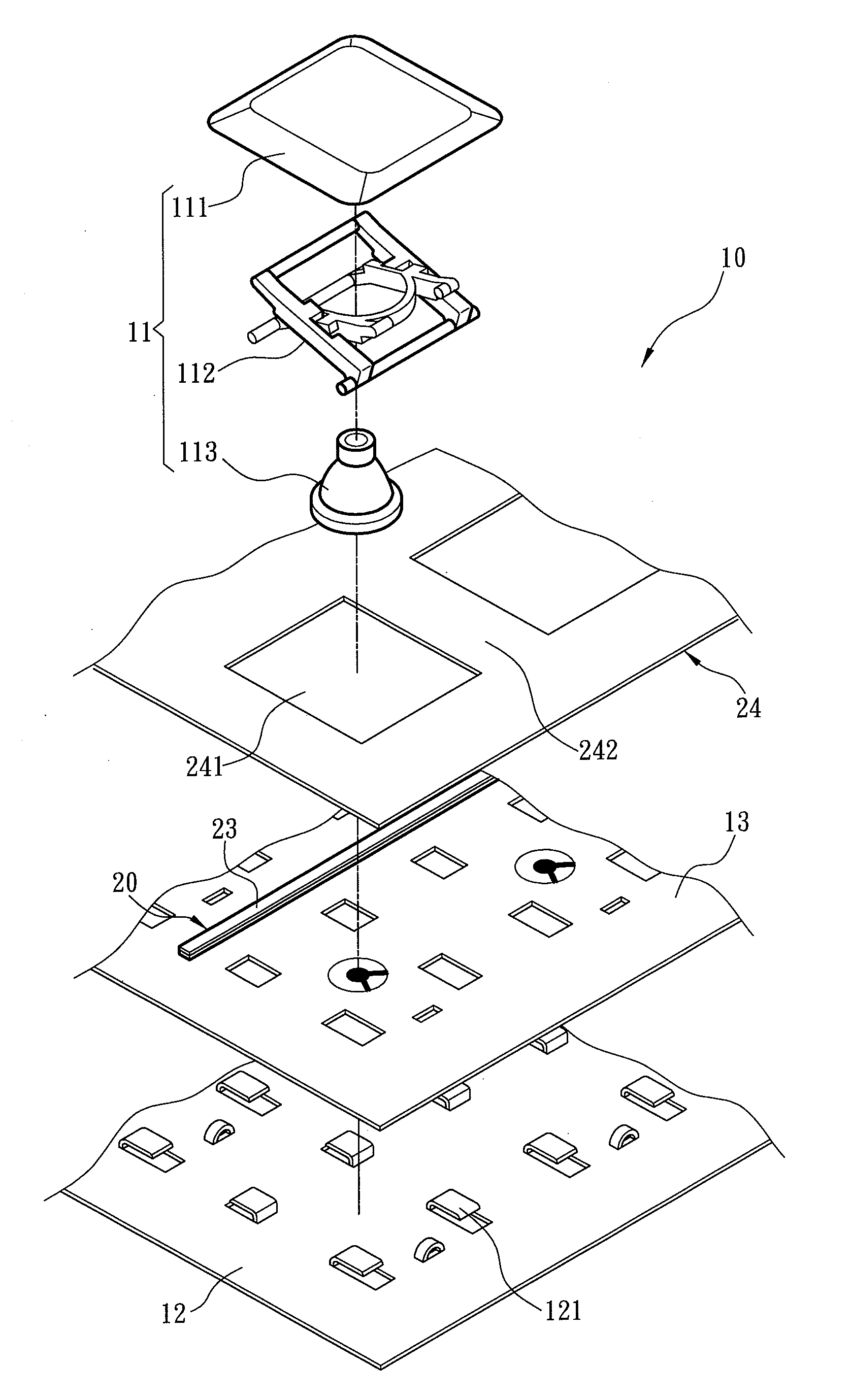
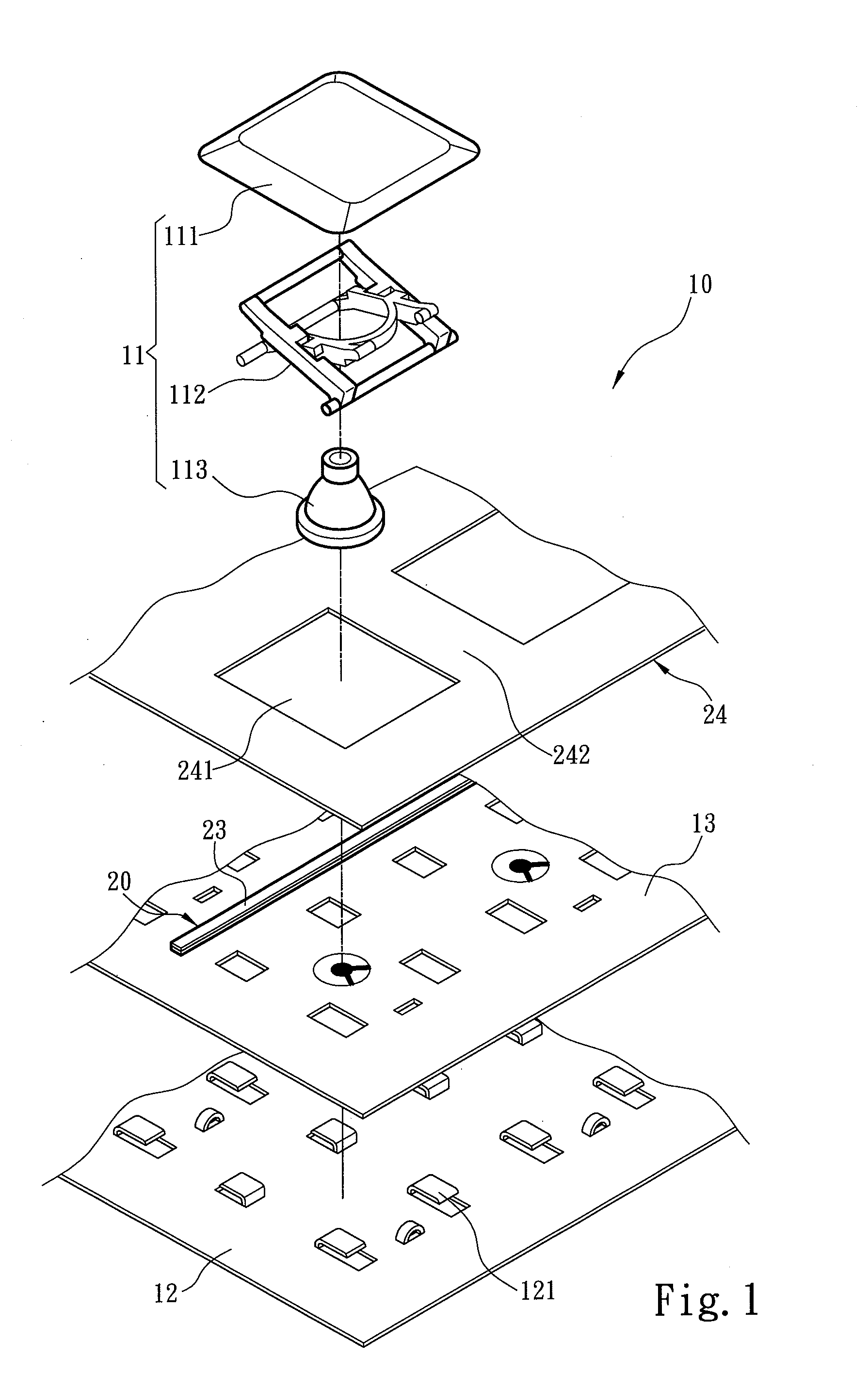
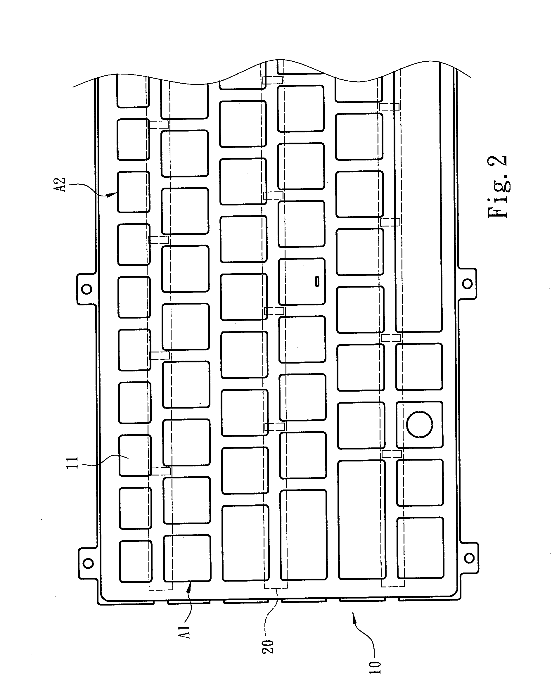
[0029]Please refer to FIGS. 1 and 2 for an embodiment of the illuminated keyboard of the invention. The illuminated keyboard includes a keyset portion 10 and at least one light source substrate 20. The keyset portion 10 includes a plurality of keys 11 and a baseboard 12 to hold the keys 11 and allow the keys 11 to respectively generate a trigger displacement. The keys 11 are arranged in parallel rows each forming a key cluster A1. Each key 11 includes a keycap 111, a driven mechanism 112 located between the keycap 111 and baseboard 12 and an elastic element 113 located in the driven mechanism 112. The elastic element 113 provides a return force to the keycap 111 to allow the key 11 to move in the trigger displacement against the baseboard 12. The baseboard 12 has at least one holding portion 121 to hold the driven mechanism 112. The keyset portion 10 includes a circuit board 13 located between the baseboard 12 and keycap 111 to generate an output command during the trigger displacem...


PUM


Abstract

An illuminated keyboard includes a keyset portion and at least one light source substrate. The keyset portion includes a plurality of keys and a baseboard to hold the keys and allow the keys to respectively generate a trigger displacement. The keys are arranged in parallel rows to form a plurality of key clusters. The light source substrate is located between any two neighboring key clusters and includes a light transmission channel with an electrode electrically connected to at least one light emitting diode (LED) and is covered by a light transmission element. The LED receives electric power provided by the light source substrate to generate light transmitted via the light transmission channel and projected uniformly to the key clusters via the light transmission element. Hence the illuminated keyboard of the invention can be made thinner and assembled simpler.

Description

FIELD OF THE INVENTION[0001]The present invention relates to an illuminated keyboard and particularly to an illuminated keyboard with a light source substrate located on a baseboard to provide uniform luminosity and can be made thinner and fabricated in simple process.BACKGROUND OF THE INVENTION[0002]Computers are widely used in people's life nowadays. The timing of using the computers also increases significantly. In order to meet these growing requirements computers have evolved from the desktop computers in the past to portable notebook computers or laptop computers, and ultrabooks now that are made in very thin as the main appeal. Whatever the types of the computers, they mostly need a keyboard to enter data or commands. As the situations of using the computer are diversified these days, in a low luminosity or dim environment without sufficient illumination people cannot make accurate keystrokes to output data correctly. In order to enable users to clearly identify legends on th...

Claims


Application Information

Patent Timeline
IPC IPC(8): G06F3/02
CPCG06F3/0202
Inventor CHOU, CHIN-WEN
Owner ZIPPY TECH
Why Eureka
Try Eureka