Pulse mode evolution difference blood pressure monitoring system

A technology of mode evolution and monitoring system, applied in vascular assessment, cardiac catheterization, etc., can solve the problems of influence of measurement results, inability to realize dynamic real-time monitoring, complex equipment structure, etc., achieving volume that is difficult to miniaturize and easy to miniaturize , the effect of complex equipment structure

Pending Publication Date: 2017-11-17
UNIV OF SHANGHAI FOR SCI & TECH
View PDF6 Cites 0 Cited by
  • Summary
  • Abstract
  • Description
  • Claims
  • Application Information

AI Technical Summary

Problems solved by technology

The prior technology and products have considerable advantages, but there are some essential deficiencies: 1) All adopt the cuff mode, and the cuff should be correctly tied on the arm when measuring, and the mood should be relaxed, and then the air in the cuff of the electronic sphygmomanometer should be exhausted Finally, it is tied to the left or right arm, which is flush with the heart. During the measurement process, the cuff is inflated and deflated. The structure of the device is complicated, the volume is difficult to miniaturize, there are many precautions during use, and it is easy to be disturbed by the outside world; 2 ) In the process of using the cuff to measure blood pressure, the human body has a certain sense of oppression, which exerts a certain pressure on the body and mind of the subject, affects the comfort of use, has a weak user experience, and has an impact on the measurement results; 3) The monitoring process takes a long time , dynamic real-time monitoring cannot be realized, and the monitoring flexibility is poor, the scope of application is limited, and the function is difficult to expand

Method used


Image

  • Pulse mode evolution difference blood pressure monitoring system

Examples


Embodiment Construction

[0014] The invention will be further described below in conjunction with the accompanying drawings and embodiments.

[0015] The pulse pattern evolution differential blood pressure monitoring system and method of the present invention adopts an adhering type non-invasive pulse parameter monitoring framework, based on the principle of direct interaction between blood vessel dynamic patterns and vascular blood physiological parameters, and collects dynamic pulse patterns at multiple points in the blood vessel area. In relation to blood physiological parameters of blood vessels, the pulse pattern space domain and time domain analysis are carried out, dynamic parameters and static parameters are separated, and blood flow parameters and blood vessel parameters are analyzed to obtain blood pressure parameters.

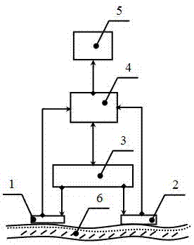
[0016] Such as figure 1 As shown, a pulse pattern evolution differential blood pressure monitoring system includes a first pulse sensor 1 , a second pulse sensor 2 , a pulse...


PUM


Abstract

The invention relates to a pulse mode evolution difference blood pressure monitoring system. Two pulse sensors are connected with a pulse sensor modulation driving module, and modulation driving signals are generated by the pulse sensor modulation driving module and sent to the pulse sensors; the pulse sensors are connected with a data analyzing and processing module, and pulse data information collected by the pulse sensors is sent to the data analyzing and processing module; the data analyzing and processing module is connected with the pulse sensor modulation driving module, and information dual-direction transmission is conducted by the data analyzing and processing module and the pulse sensor modulation driving module; the data analyzing and processing module is connected with a parameter interface module, mode evolution difference is adopted by the data analyzing and processing module to analyze blood flow parameters and vascular parameters, blood pressure parameters obtained through analyzing are sent to the parameter interface module, and monitored blood pressure parameters are output by the parameter interface module. The system has the advantages of high monitoring precision, real-time monitoring, good consistency, high anti-interference performance and high reliability.

Description

technical field [0001] The present invention relates to a blood pressure monitoring system, especially a blood pressure monitoring system applied in the fields of blood vessel examination, health monitoring, medical diagnosis, health management, life science, biotechnology, human-computer interaction, behavioral organization, psychology, intelligent perception, etc. A model evolution differential blood pressure monitoring system belongs to the technical field of blood pressure monitoring. Background technique [0002] Hypertension is the most common chronic non-communicable disease and the most important risk factor for cardiovascular and cerebrovascular diseases. According to the "China Cardiovascular Disease Report": In 2010, China had a total of 2.043 million deaths due to hypertension (1.154 million men and 889,000 women), accounting for 24.6% of all deaths; In 2002 and 2002, four nationwide sampling surveys on hypertension were conducted, and the prevalence rates of hy...

Claims


Application Information

Patent Timeline
IPC IPC(8): A61B5/021
CPCA61B5/02108A61B5/02141
Inventor 高秀敏单新治苗玉王冠学曾祥堉包颖
Owner UNIV OF SHANGHAI FOR SCI & TECH
Why Eureka
Try Eureka