Image blur correction apparatus and imaging apparatus

a technology of image blur correction and imaging apparatus, which is applied in the direction of optics, instruments, optical elements, etc., can solve the problems of low degree of design freedom regarding arrangement, and achieve the effect of smooth turning, increased degree of freedom, and smooth operation of blur correction operation

Active Publication Date: 2013-12-05
SONY CORP
View PDF5 Cites 2 Cited by
  • Summary
  • Abstract
  • Description
  • Claims
  • Application Information

AI Technical Summary

Benefits of technology

[0038]Therefore, in the image blur correction apparatus, there is an increased degree of freedom in the arrangement of coupling member, the first drive motor, and the second drive motor, and the lens unit can be smoothly turned with respect to the fixed member by the first tolerance portion and the second tolerance portion, so that the blur correction operation can be carried out more smoothly while ensuring a degree of design freedom.

Problems solved by technology

Therefore, each of the parts unfortunately has to be arranged on the outer periphery side of the lens unit, which means that the degree of design freedom regarding arrangement is low.

Method used


Image

  • Image blur correction apparatus and imaging apparatus
  • Image blur correction apparatus and imaging apparatus
  • Image blur correction apparatus and imaging apparatus

Examples


first modified example

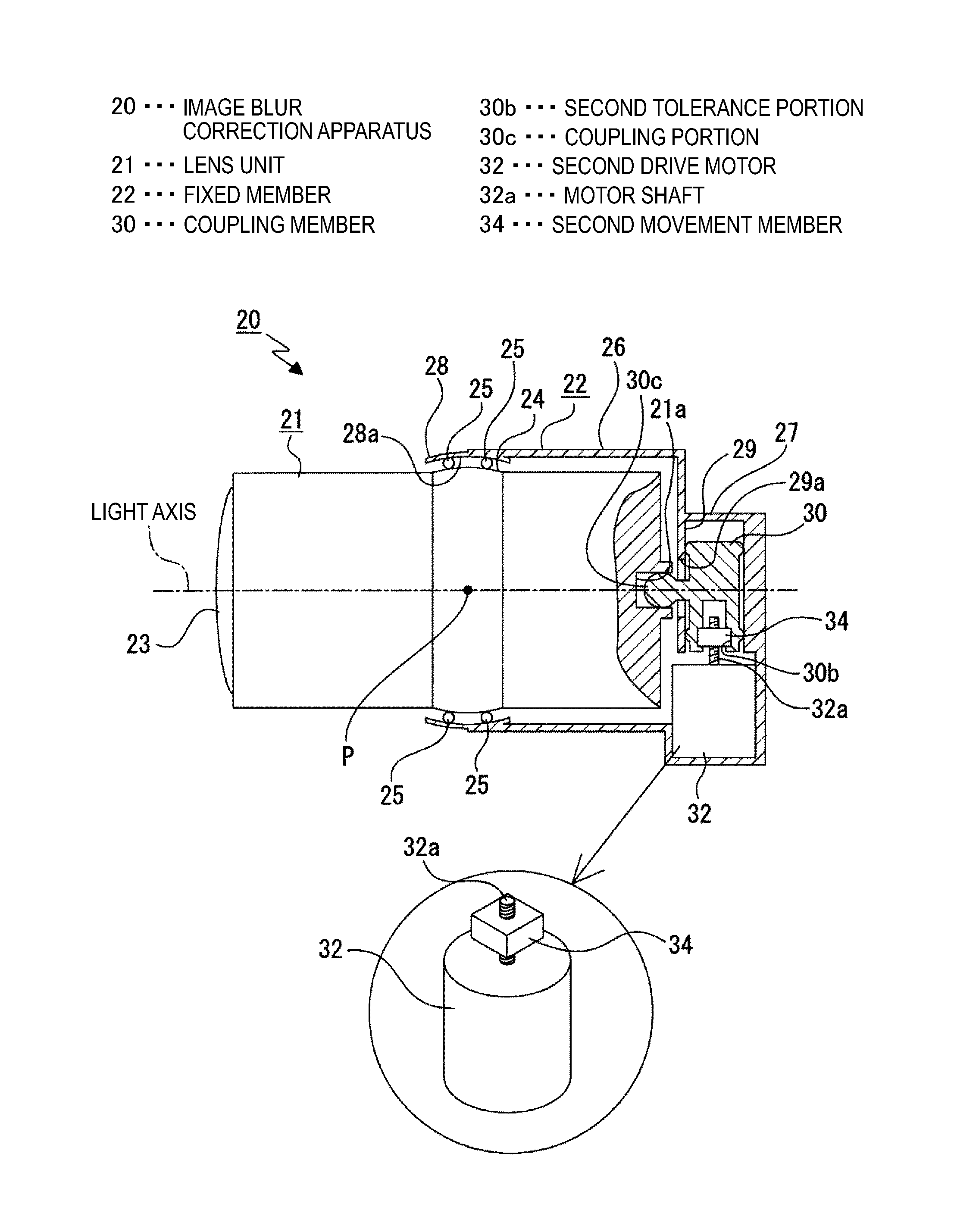
[0123]First, an image blur correction apparatus 20A according to a first modified example will be described (refer to FIGS. 14 and 15).

[0124]The image blur correction apparatus 20A has a lens unit 21A and a fixed member 22A that supports the lens unit 21A.

[0125]A concave coupling portion 21a open to the side is formed on the lens unit 21A.

[0126]The fixed member 22A is provided with a holding portion 27A to the side of the lens unit 21A.

[0127]The lens unit 21A can be turned with respect to the fixed member 22A in the first direction (yaw direction) and in the second direction (pitch direction).

[0128]The coupling member 30 is movably supported in the front / rear direction and the vertical direction on the holding portion 27A of the fixed member 22A. The coupling portion 30c protruding toward the side is provided on the coupling member 30.

[0129]The coupling portion 30c of the coupling member 30 is inserted through the concave coupling portion 21a, thereby being coupled to the lens unit ...

second modified example

[0134]Next, an image blur correction apparatus 20B according to a second modified example will be described (refer to FIGS. 16 and 17).

[0135]The image blur correction apparatus 20B has a lens unit 21B and a fixed member 22B that supports the lens unit 21B.

[0136]A concave coupling portion 21a open to the side is formed on the lens unit 21B.

[0137]The fixed member 22B is provided with a holding portion 27B to the side of the lens unit 21B.

[0138]The lens unit 21B can be turned with respect to the fixed member 22B in the first direction (yaw direction) and in the second direction (pitch direction).

[0139]The coupling member 30 is movably supported in the horizontal direction and the vertical direction on the holding portion 27B of the fixed member 22B. The coupling portion 30c protruding toward the side is provided on the coupling member 30.

[0140]The coupling portion 30c of the coupling member 30 is inserted through the concave coupling portion 21a, thereby being coupled to the lens unit ...

third modified example

[0145]Next, an image blur correction apparatus 20C according to a first modified example will be described (refer to FIGS. 18 to 25).

[0146]The image blur correction apparatus 20C has a lens unit 21C and a fixed member 22C that supports the lens unit 21C (refer to FIGS. 18 and 19).

[0147]A concave coupling portion 21a open to the side is formed on the lens unit 21C. The center of the concave coupling portion 21a is in line with the second axis.

[0148]The fixed member 22C is provided with a holding portion 27C to the side of the lens unit 21C.

[0149]The lens unit 21C can be turned with respect to the fixed member 22C in the first direction (yaw direction) and in a third direction (roll direction).

[0150]The coupling member 30 is movably supported in the front / rear direction and the vertical direction on the holding portion 27C of the fixed member 22C. The coupling portion 30c that protrudes toward the side is provided on the coupling member 30.

[0151]The coupling member 30 is movably suppo...


PUM


Abstract

Provided is an image blur correction apparatus including a lens unit configured to include at least one lens and configured to be turnable in two different directions using, as supporting points, two axes that are orthogonal to an outer housing, a fixed member configured to turnably support the lens unit in the two directions, a first drive motor configured to be mounted on the fixed member and configured to turn the lens unit in one of the two directions, a second drive motor configured to be mounted on the fixed member and configured to turn the lens unit in another of the two directions, and a coupling member configured to be coupled to the first drive motor and the second drive motor and configured to include a coupling portion.

Description

BACKGROUND[0001]The present technology relates to a technical field regarding image blur correction apparatuses and imaging apparatuses. More specifically, the present technology relates to a technical field for making a blur correction operation smoother while also ensuring a degree of design freedom by providing a first drive motor, a second drive motor, and a coupling member by which these two drive motors are coupled, and forming a tolerance portion on the coupling member that allows a lens unit to turn.[0002]In an imaging apparatus such as a video camera and a still camera, an image blur correction apparatus may be provided for correcting image blur by moving a lens in a direction orthogonal to the light axis direction.[0003]The image blur correction apparatus provided in such an imaging apparatus may be configured so that a lens unit, which has a lens, turns in a first direction which is a direction about a first axis with respect to an outer housing, and in a second direction...

Claims


Application Information

Patent Timeline
Patent Type & Authority Applications(United States)
IPC IPC(8): G02B27/64
CPCG02B27/646G03B2205/0023
Inventor NAKAYAMA, TATSUYUKI
Owner SONY CORP
Why Eureka
Try Eureka