Fluid control apparatus and method for adjusting fluid control apparatus

a fluid control apparatus and fluid control technology, applied in the direction of machines/engines, flexible member pumps, positive displacement liquid engines, etc., can solve the problems reducing the capacity (flow rate and pressure) of the fluid pump, and limiting the fluid pump having an existing structure. , to achieve the effect of increasing the temperature of the fluid control apparatus and facilitating the inspection step in a short tim

Active Publication Date: 2013-12-05
MURATA MFG CO LTD
View PDF18 Cites 40 Cited by
  • Summary
  • Abstract
  • Description
  • Claims
  • Application Information

AI Technical Summary

Benefits of technology

[0050]Thus, when the interval from the diaphragm to the flexible plate is increased, the discharge pressure of the fluid control apparatus exhibits a value close to the discharge pressure of the fluid control apparatus at a temperature higher than normal temperature.
[0051]Therefore, in measuring a discharge pressure at a temperature higher than normal temperature is measured, it is necessary to measure the pump pressure of the fluid control apparatus after the fluid control apparatus is driven for a long time period and the temperature of the fluid control apparatus is increased by generated heat. However, in this method, by applying the drive voltage to the driver, it is possible to measure, in a pseudo manner, a discharge pressure at a temperature higher than normal temperature. Thus, it is possible to conduct the inspecting step in a short time.
[0052]According to various preferred embodiments of the present invention, it is possible to adjust the natural vibration frequency of the flexible plate to an optimum value at which a desired discharge pressure equal to or higher than the predetermined value is obtained with power consumption within an allowable range.

Problems solved by technology

However, an electronic apparatus into which the fluid pump is incorporated constantly tends to be decreased in size, and thus the fluid pump is required to be further decreased in size without diminishing the capability (flow rate and pressure) of the fluid pump.
Thus, when it is attempted to decrease the size of the pump with its capability maintained, there is a limit on the fluid pump having an existing structure.
However, the shape of each component constituting the fluid pump 901 is varied for each fluid pump 901, and there is a limit on the accuracy of positioning when each component is laminated.

Method used


Image

  • Fluid control apparatus and method for adjusting fluid control apparatus
  • Fluid control apparatus and method for adjusting fluid control apparatus
  • Fluid control apparatus and method for adjusting fluid control apparatus

Examples


Embodiment Construction

[0065]Hereinafter, a piezoelectric pump 101 according to preferred embodiments of the present invention will be described.

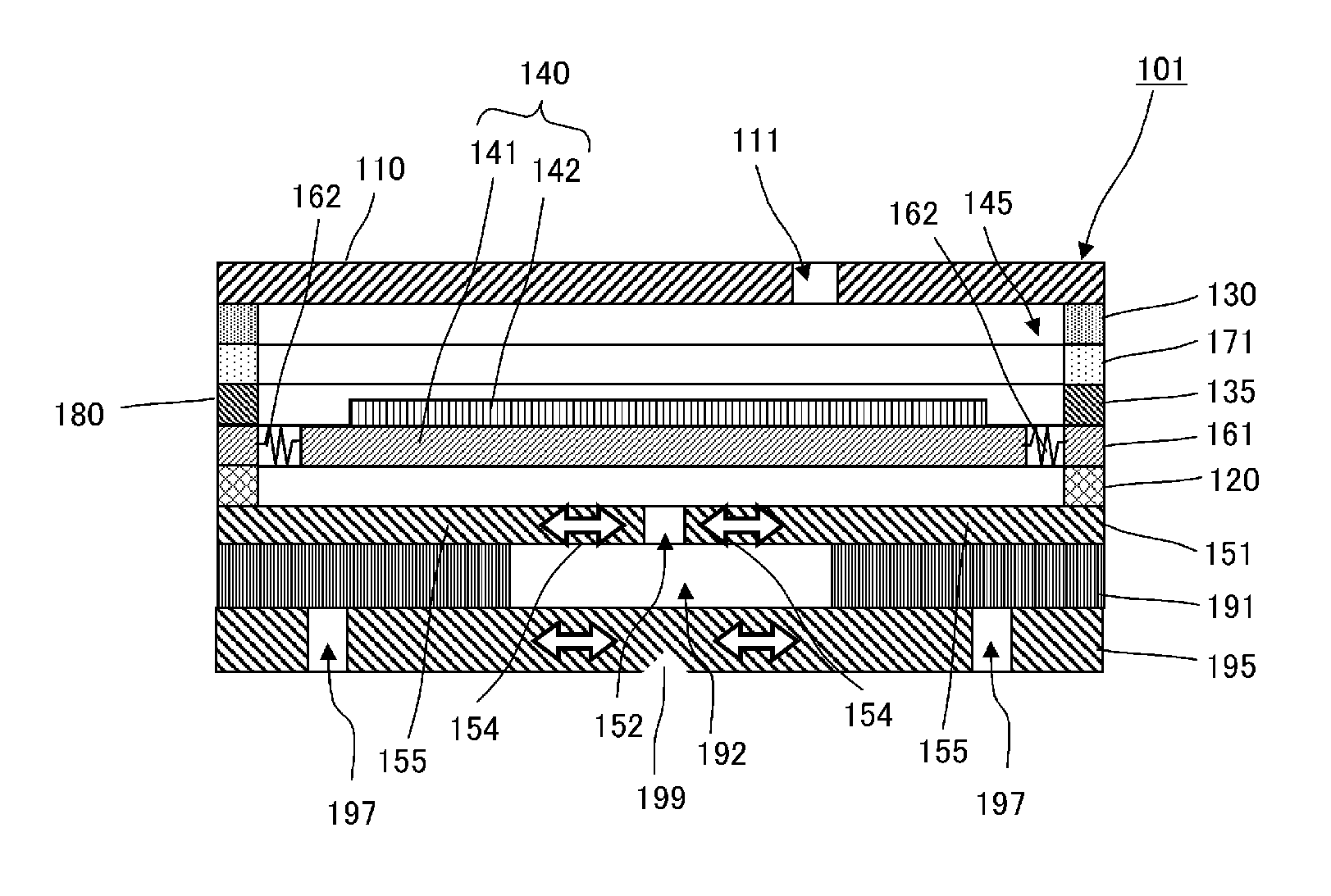
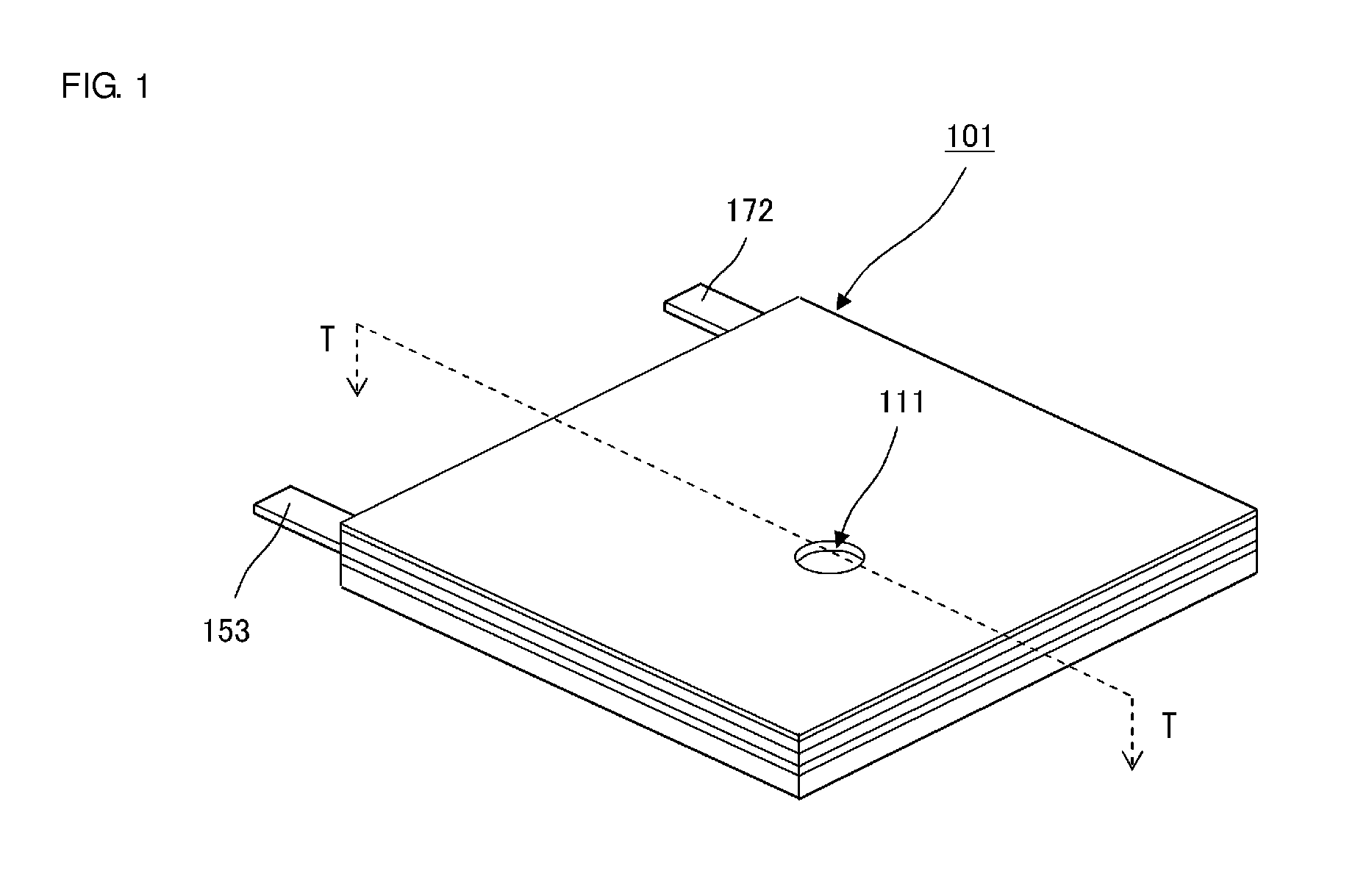
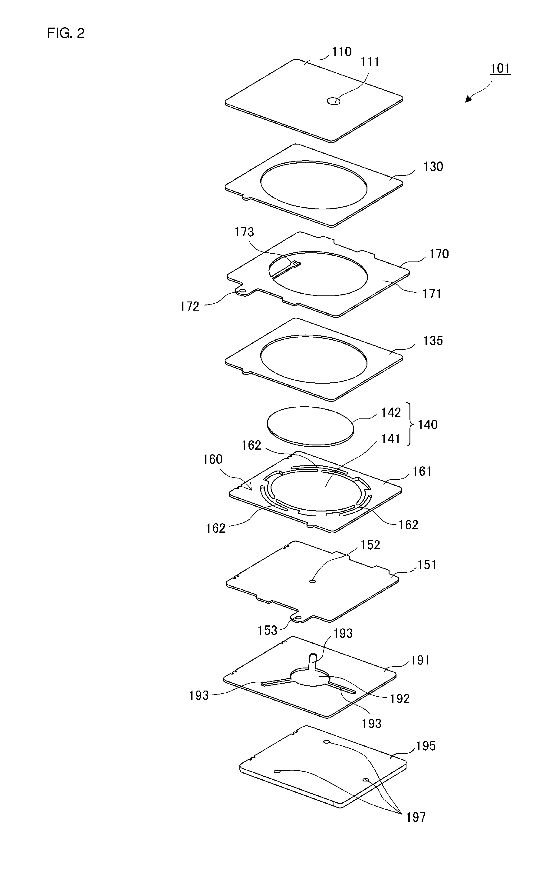
[0066]FIG. 1 is an external perspective view of the piezoelectric pump 101 according to a preferred embodiment of the present invention. FIG. 2 is an exploded perspective view of the piezoelectric pump 101 shown in FIG. 1, and FIG. 3 is a cross-sectional view of the piezoelectric pump 101 shown in FIG. 1, taken along a line T-T.

[0067]As shown in FIG. 2, the piezoelectric pump 101 includes a cover plate 195, a base plate 191, a flexible plate 151, a diaphragm unit 160, a piezoelectric device 142, a spacer 135, an electrode conducting plate 170, a spacer 130, and a cover portion 110, and has a structure in which these components are laminated in order.

[0068]A diaphragm 141 includes an upper surface on which the piezoelectric device 142 is provided and a lower surface that faces the flexible plate 151. The piezoelectric device 142 is adhesively fixed to the upper su...


PUM


Abstract

In a method for adjusting a fluid control apparatus, in a pressing step, a piezoelectric pump is placed on a stage with a cover plate facing upward, the stage is moved up, and a center portion of a principal surface of the cover plate on a side opposite to a diaphragm is pressed with a pressing pin. As a result, the cover plate and the base plate are shaped so as to warp convexly toward the diaphragm side, and a portion joined to a flexible plate is pulled, such that the flexible plate is caused to warp convexly toward the diaphragm side. Thus, residual tensile stress occurs in a movable portion of the flexible plate. Therefore, due to the residual tensile stress, the tensile stress of the movable portion of the flexible plate is increased.

Description

BACKGROUND OF THE INVENTION[0001]1. Field of the Invention[0002]The present invention relates to a fluid control apparatus that performs fluid control and a method for adjusting the fluid control apparatus.[0003]2. Description of the Related Art[0004]PCT Publication No. 2008 / 069264 discloses an existing fluid pump.[0005]FIG. 10 is a diagram showing a pumping action of the fluid pump in PCT Publication No. 2008 / 069264 in a third-order resonant mode. The fluid pump shown in FIG. 10 includes a pump body 10, a diaphragm 20 fixed at its outer peripheral portion to the pump body 10, a piezoelectric device 23 attached to a center portion of the diaphragm 20, a first opening 11 formed in a portion of the pump body 10 that faces substantially the center portion of the diaphragm 20, and a second opening 12 formed in an intermediate region between the center portion and the outer peripheral portion of the diaphragm 20 or in a portion of the pump body that faces the intermediate region. The dia...

Claims


Application Information

Patent Timeline
Patent Type & Authority Applications(United States)
IPC IPC(8): F04B43/04
CPCF04B43/04F04B43/046
Inventor HIRATA, ATSUHIKOOMORI, KENTA
Owner MURATA MFG CO LTD
Why Eureka
Try Eureka