
Chest Compression Belt with Belt Position Monitoring System

a belt position monitoring and chest compression technology, applied in the field of chest compression devices, can solve the problems of inferior/superior movement of the belt by cpr providers using the device, the inability of experienced paramedics to maintain adequate chest compression for more than a few minutes, and the inability of cpr to sustain or revive patients

Inactive Publication Date: 2013-12-05
ZOLL MEDICAL CORPORATION
View PDF2 Cites 32 Cited by
  • Summary
  • Abstract
  • Description
  • Claims
  • Application Information

AI Technical Summary

Benefits of technology

The patent text describes a system for performing CPR that adjusts compression depth based on the patient's shape. The system uses distance sensors to measure the size and shape of the patient's chest and uses accelerometers to measure the force applied to the chest. This allows the control system to determine the relationship between the compression depth and the force applied to the chest, and adjust the target compression depth accordingly. This system ensures effective CPR for patients of different shapes.

Problems solved by technology

However, even experienced paramedics cannot maintain adequate chest compressions for more than a few minutes.
Thus, CPR is not often successful at sustaining or reviving the patient.
During the course of automated chest compression using the AutoPulse® chest compression device, CPR providers using the device may be concerned about inferior / superior movement of the belt.
None of the references discussed above provide a means for detecting horizontal displacement or non-uniformity in the downward movement of a compression component of an automated chest compression device.
Proper depth of compression, inadequate or excessive compression, and inferior / superior slippage of the compression belt or load distributing panels, and even changes of the patient's chest caused by the compressions can be detected.
For example, the system may interrupt compressions if significant slippage is detected, and / or notify an EMT or other CPR provider that the compression belt has slipped out of place.

Method used


Image

  • Chest Compression Belt with Belt Position Monitoring System
  • Chest Compression Belt with Belt Position Monitoring System
  • Chest Compression Belt with Belt Position Monitoring System

Examples


Embodiment Construction

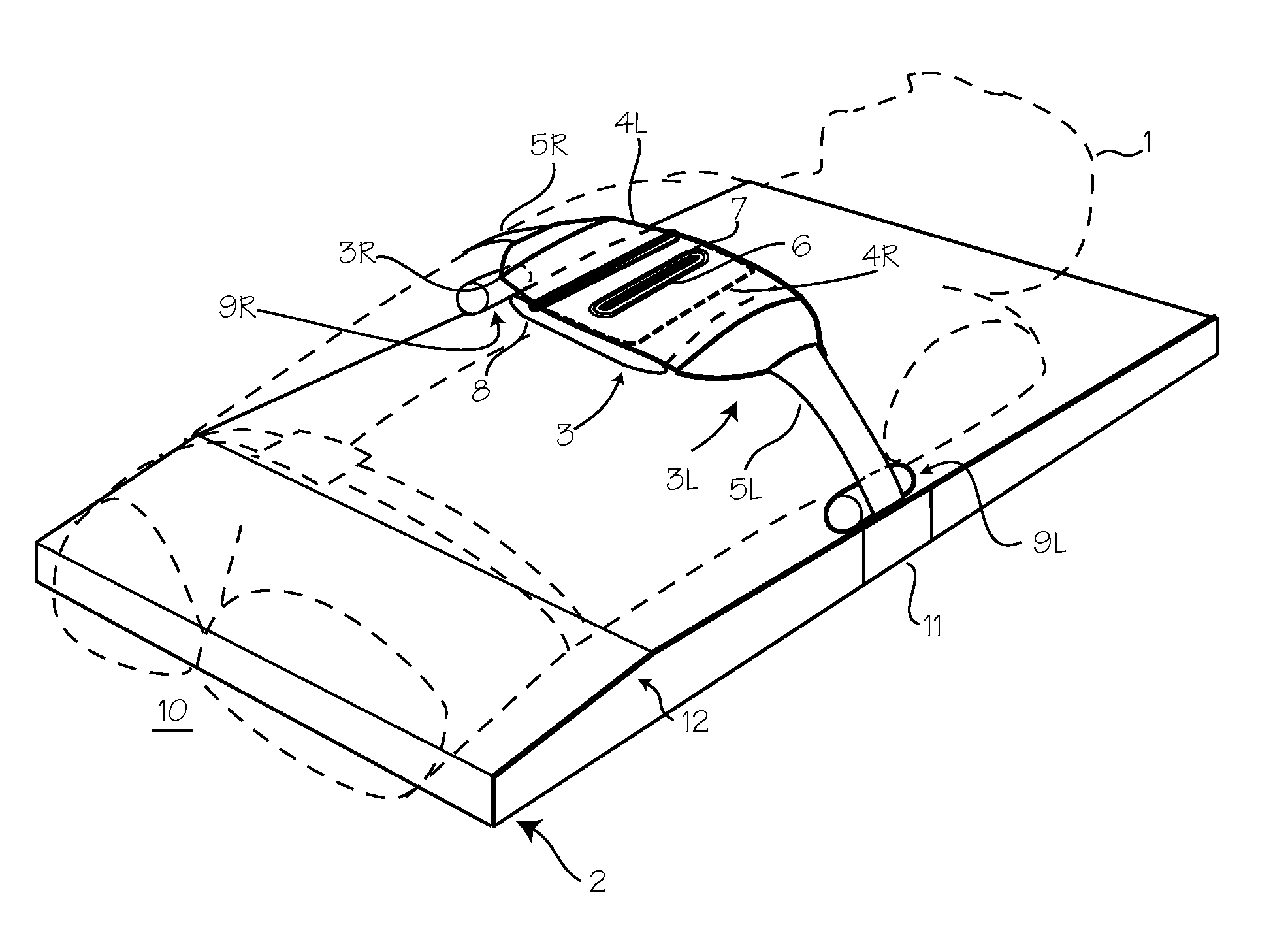
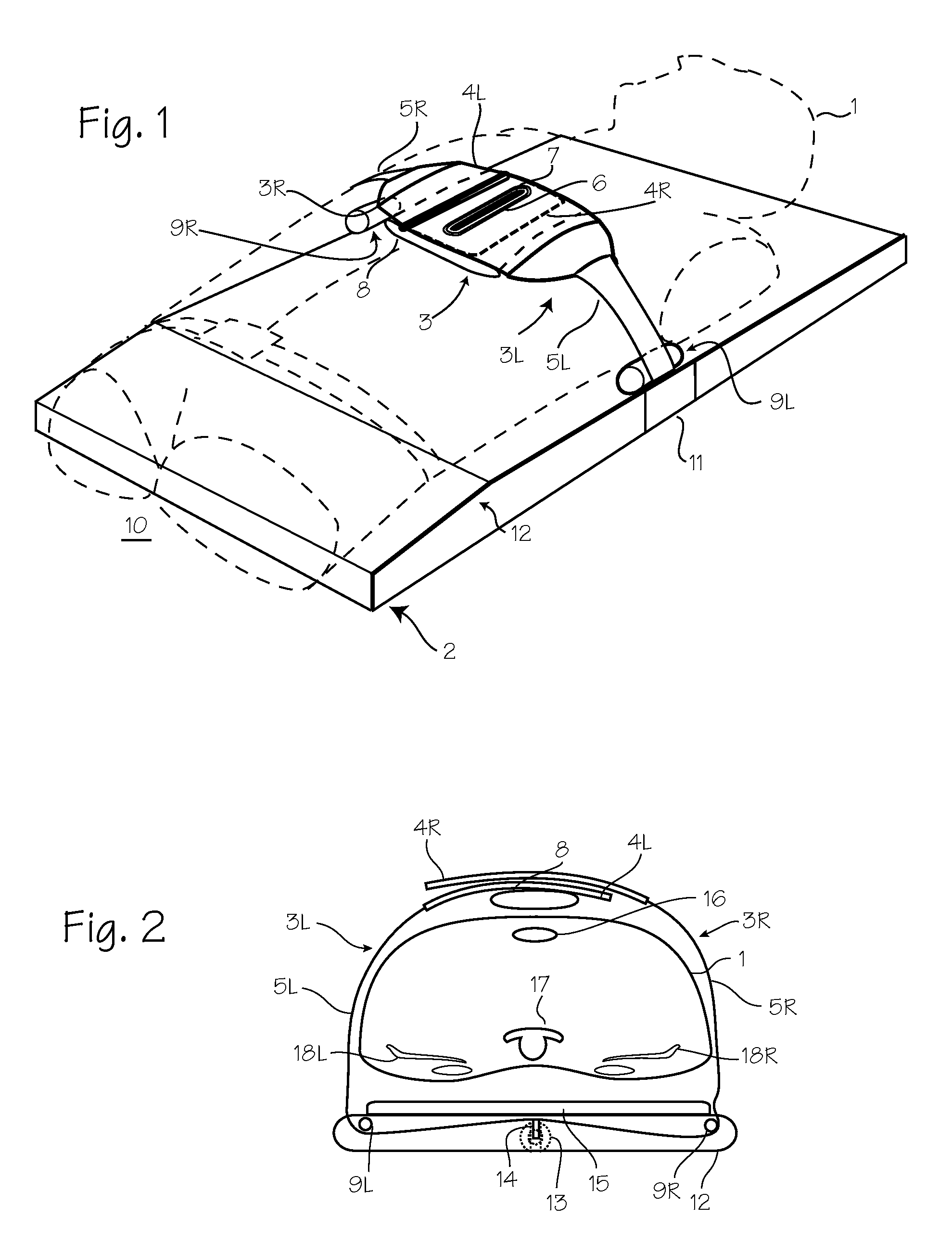
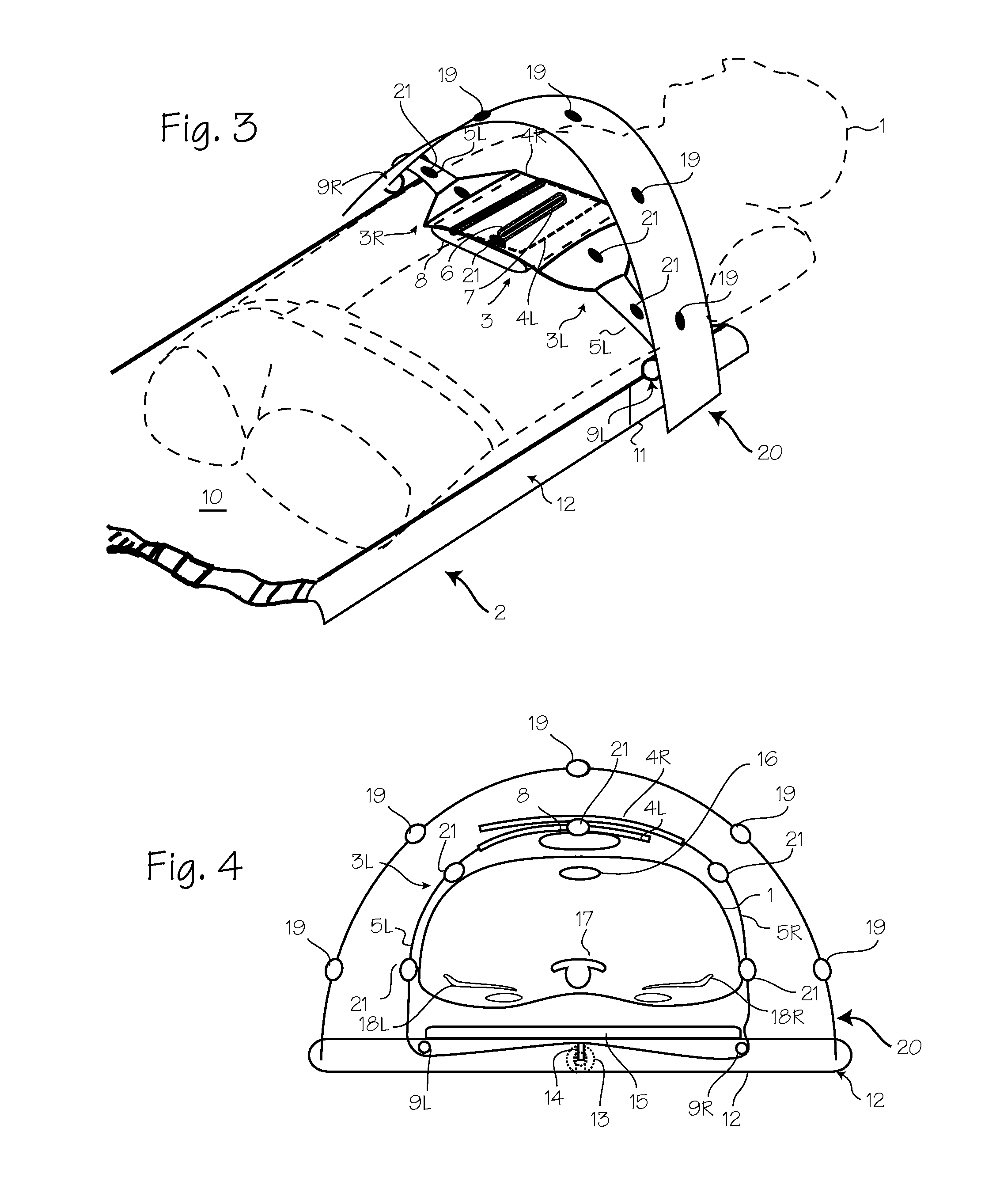
[0033]FIGS. 1 and 2 illustrate the chest compression device, similar to the AutoPulse® CPR chest compression device, fitted on a patient 1. A chest compression device 2 applies compressions with the belt 3, which has a right belt portion 3R and a left belt portion 3L, including load distributing panels 4R and 4L designed for placement over the anterior surface of the patient's chest while in use, and tensioning portions which extend from the load distributing portions to a drive spool, shown in the illustration as narrow pull straps 5R and 5L. (The entirety of the compression belt is referred to as a “load distributing band” in the art.) The right belt portion and left belt portion are secured to each other with hook and loop fasteners and aligned with the eyelet 6 and protrusion 7. A bladder 8 is disposed between the belt and the chest of the patient. The narrow pull straps 5R and 5L of the belt are spooled onto a drive spool located within the platform (shown in FIG. 2) to tighten...


PUM


Abstract

An automated chest compression device for performing CPR, with distance sensors disposed on a compressing mechanism and on a structure fixed relative to the CPR patient, for determining inferior / superior movement of the compressing mechanism over the course of multiple compressions.

Description

[0001]This application claims priority to U.S. Provisional Application 61 / 654,642 filed Jun. 1, 2012.FIELD OF THE INVENTIONS[0002]The inventions described below relate to the field of CPR chest compression devices.BACKGROUND OF THE INVENTIONS[0003]Cardiopulmonary resuscitation (CPR) is a well-known and valuable method of first aid used to resuscitate people who have suffered from cardiac arrest. CPR requires repetitive chest compressions to squeeze the heart and the thoracic cavity to pump blood through the body. Artificial respiration, such as mouth-to-mouth breathing or a bag mask apparatus, is used to supply air to the lungs. When a first aid provider performs manual chest compression effectively, blood flow in the body is about 25% to 30% of normal blood flow. However, even experienced paramedics cannot maintain adequate chest compressions for more than a few minutes. Hightower, et al., Decay In Quality Of Chest Compressions Over Time, 26 Ann. Emerg. Med. 300 (Sep. 1995). Thus, ...

Claims


Application Information

Patent Timeline
IPC IPC(8): A61H31/00
CPCA61H31/006A61H31/00A61H31/005A61H31/008A61H2011/005A61H2031/002A61H2031/003A61H2201/0161A61H2201/0173A61H2201/0184A61H2201/1215A61H2201/1664A61H2201/5007A61H2201/5043A61H2201/5046A61H2201/5048A61H2201/5058A61H2201/5064A61H2201/5084A61H2201/5092A61H2201/5097A61H2205/083A61H2230/04A61N1/0492A61N1/39044
Inventor HERKEN, ULRICH R.FREEMAN, GARY A.
Owner ZOLL MEDICAL CORPORATION
Learn More