Methods and Devices for Forming Bone Tunnels

a bone tunnel and bone tunnel technology, applied in the field of bone tunnel forming methods and devices, can solve the problems of difficult and tedious bone tunneling process, difficult to achieve proper trajectories of holes, time-consuming tissue and suture manipulation,

Active Publication Date: 2013-12-05
DEPUY SYNTHES PROD INC
View PDF3 Cites 38 Cited by
  • Summary
  • Abstract
  • Description
  • Claims
  • Application Information

AI Technical Summary

Benefits of technology

[0020]In another embodiment, a surgical method is provided that includes forming a bone tunnel in bone, forming a first transverse tunnel in the bone, and forming a second transverse tunnel in the bone. The first transverse tunnel can intersect the bone tunnel, and the second transverse tunnel can intersect the bone tunnel. A first suture can be positioned through the anterior-posterior tunnel and through the first transverse tunnel such that a first portion of the first suture extends out of the first transverse tunnel and a second portion of the first suture extends out of the bone tunnel. A second suture can be positioned through the bone tunnel and through the second transverse tunnel such that a first portion of the second suture extends out of the second transverse tunnel and a second portion ...

Problems solved by technology

In either procedure, the knotting process can be difficult and tedious, particularly during laparoscopic or arthroscopic procedures, where the surgeon must remotely manipulate the suture using tools inserted through an access tube.
Additionally, passing one or more sutures through the tissue can require extensive, time-consuming manipulation of the tissue and suture(s).
However, it can be difficult to achieve the proper trajectories of the holes so they con...

Method used


Image

  • Methods and Devices for Forming Bone Tunnels
  • Methods and Devices for Forming Bone Tunnels
  • Methods and Devices for Forming Bone Tunnels

Examples


Embodiment Construction

[0070]Certain exemplary embodiments will now be described to provide an overall understanding of the principles of the structure, function, manufacture, and use of the devices and methods disclosed herein. One or more examples of these embodiments are illustrated in the accompanying drawings. Those of ordinary skill in the art will understand that the devices and methods specifically described herein and illustrated in the accompanying drawings are non-limiting exemplary embodiments and that the scope of the present invention is defined solely by the claims. The features illustrated or described in connection with one exemplary embodiment may be combined with the features of other embodiments. Such modifications and variations are intended to be included within the scope of the present invention.

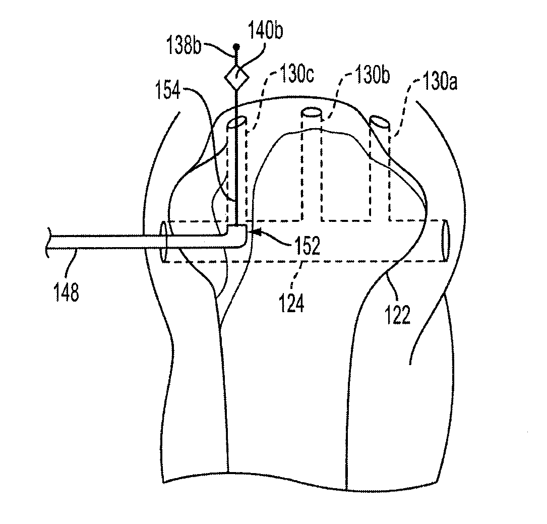
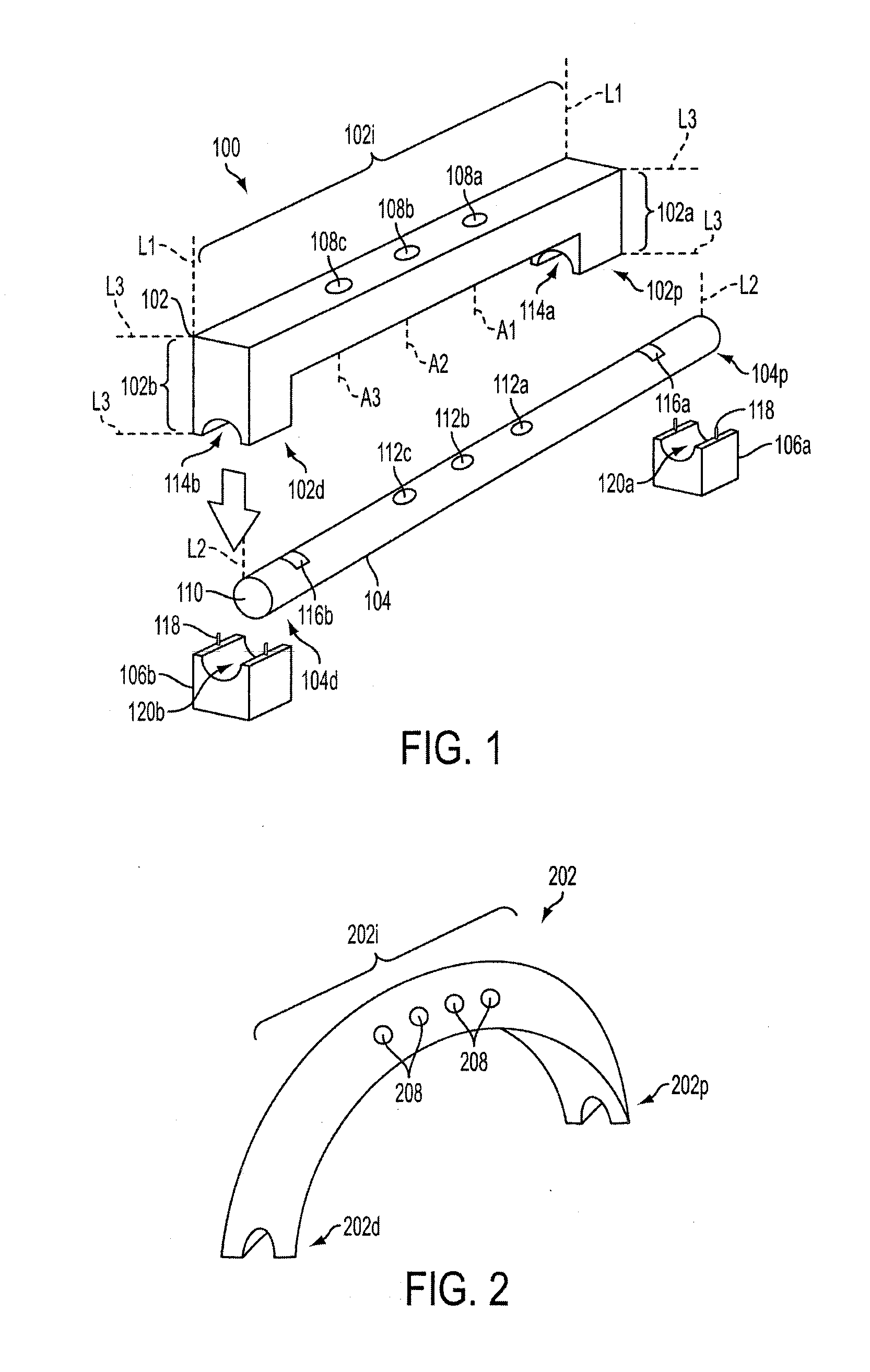
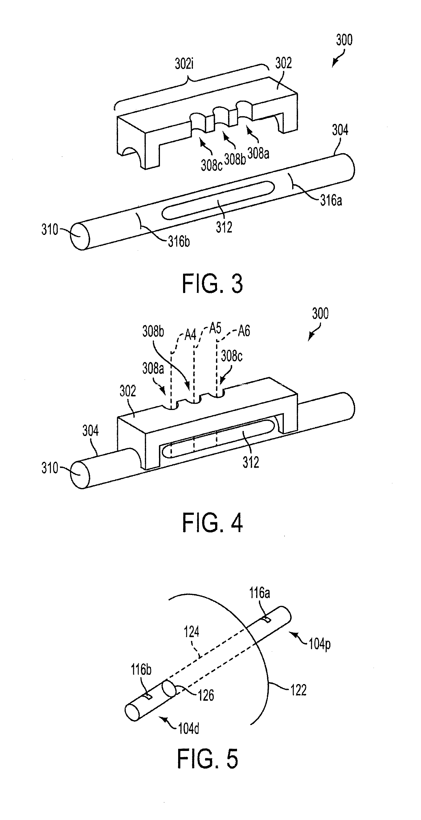
[0071]Various exemplary methods and devices are provided for forming bone tunnels. In general, the methods and devices can allow multiple converging tunnels to be formed in bone, such as in ...


PUM


Abstract

Methods and devices are provided for forming bone tunnels. In general, the methods and devices allow multiple converging tunnels to be formed in bone, such as in an arthroscopic surgical procedure, e.g., a rotator cuff repair surgical procedure. One or more sutures can be advanced through the converging tunnels, and the suture(s) can be coupled to tissue. The suture(s) with the tissue coupled thereto can be tensioned, thereby helping to maximize an amount of the tissue in contact with the bone. In an exemplary embodiment, a guide device is provided that can be configured to allow a first tunnel to be formed in bone and to allow a plurality of additional tunnels to be formed in the bone at predetermined angular positions relative to the first tunnel such that each of the additional tunnels can extend transverse to the first tunnel and intersect the first tunnel.

Description

FIELD OF THE INVENTION[0001]The present invention relates generally to methods and devices for forming bone tunnels, and in particular to forming intersecting bone tunnels.BACKGROUND OF THE INVENTION[0002]Soft tissues, such as ligaments, tendons and muscles, are attached to a large portion of the human skeleton. In particular, many ligaments and tendons are attached to the bones which form joints, such as shoulder and knee joints. A variety of injuries and conditions require attachment or reattachment of a soft tissue to bone. For example, when otherwise healthy tissue has been torn away from a bone, surgery is often required to reattach the tissue to the bone to allow healing and a natural reattachment to occur.[0003]A variety of injuries and conditions require repair of soft tissue damage, or reattachment of soft tissue to bone and / or surrounding tissue. One example of otherwise healthy tissue being torn away from a bone is a shoulder rotator cuff tendon being partially or complet...

Claims


Application Information

Patent Timeline
IPC IPC(8): A61B17/16A61B17/04A61B17/56
CPCA61B17/1796A61B17/0482A61B17/0485A61B17/16A61B17/1684A61B17/1714A61B17/1778A61B17/86A61B17/8875A61B2017/00407A61F2/0811A61F2002/0852A61F2002/0882A61F2002/0888
Inventor CLEVELAND, BENJAMINDIMATTEO, KRISTIANSOJKA, ERIK S.WEINERT, CHRISTOPHER G.LIZARDI, JOSE E.
Owner DEPUY SYNTHES PROD INC
Why Eureka
Try Eureka