
Method and System for Mitigating Impact of Malfunction in Actual Load Determination on Peak Load Management

a technology of actual load determination and peak load management, applied in the field of power management, can solve the problems of reducing cost savings, affecting actual load determination, and causing the actual load to be overestimated, so as to reduce cost savings and mitigate the impact of peak load managemen

Inactive Publication Date: 2013-12-05
NANTENERGY INC
View PDF8 Cites 7 Cited by
  • Summary
  • Abstract
  • Description
  • Claims
  • Application Information

AI Technical Summary

Benefits of technology

The present invention substitutes a predicted load for the actual load during a malfunction in determining the load. This avoids using an inaccurate actual load, which could lead to suboptimal use of battery power and cost savings. The technical effect is improved peak load management.

Problems solved by technology

Otherwise, the management system may discharge stored power from the battery system too early or too late, resulting in an elevated peak load and reduced cost savings.
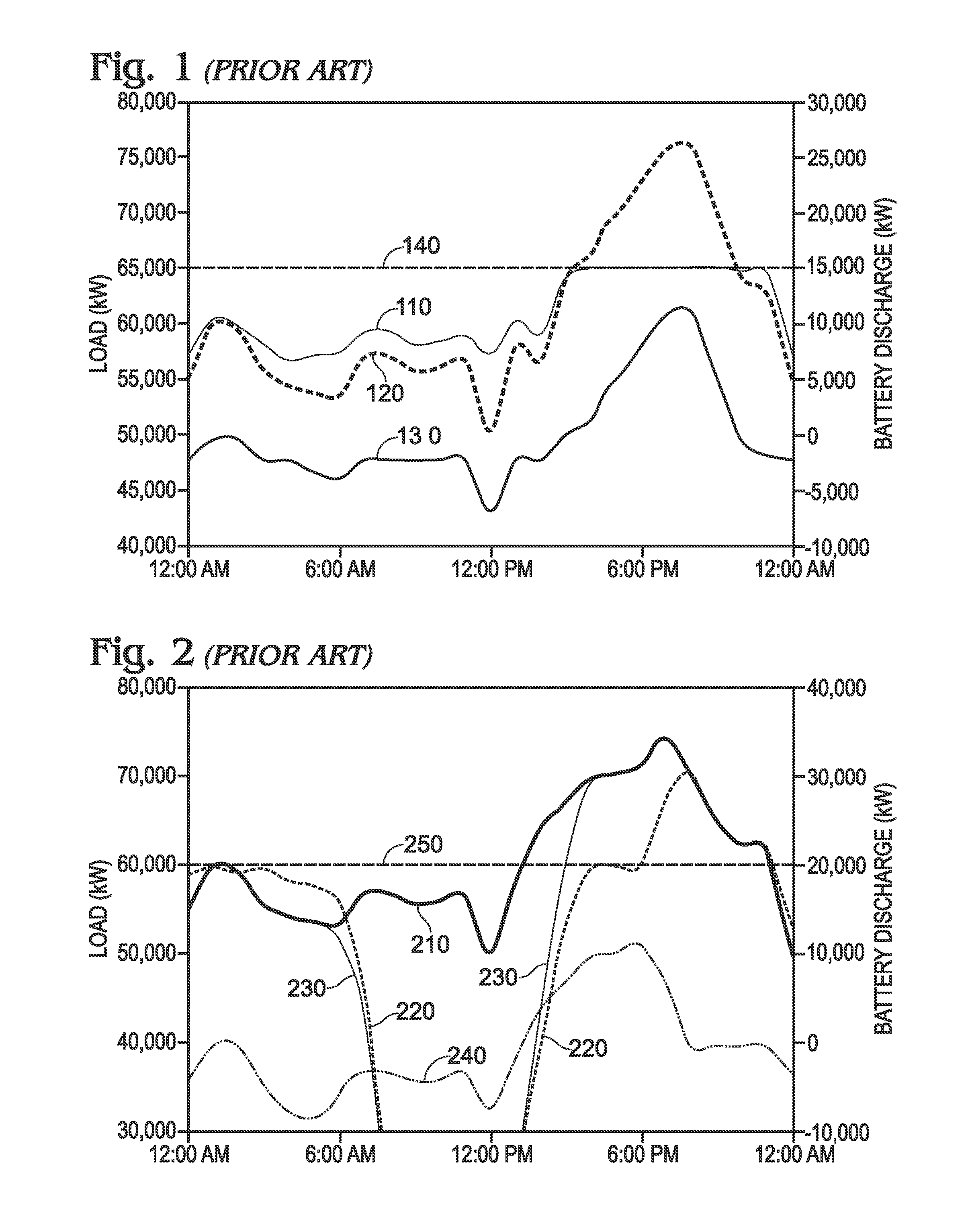
However, due to failure to account for power generated at the site, the management system sees an erroneous actual load 210 that grossly overestimates true actual load 230.
Such a failure might result from malfunction of a meter that measures power generation at the site or of a communications channel between such a meter and a peak load management controller.
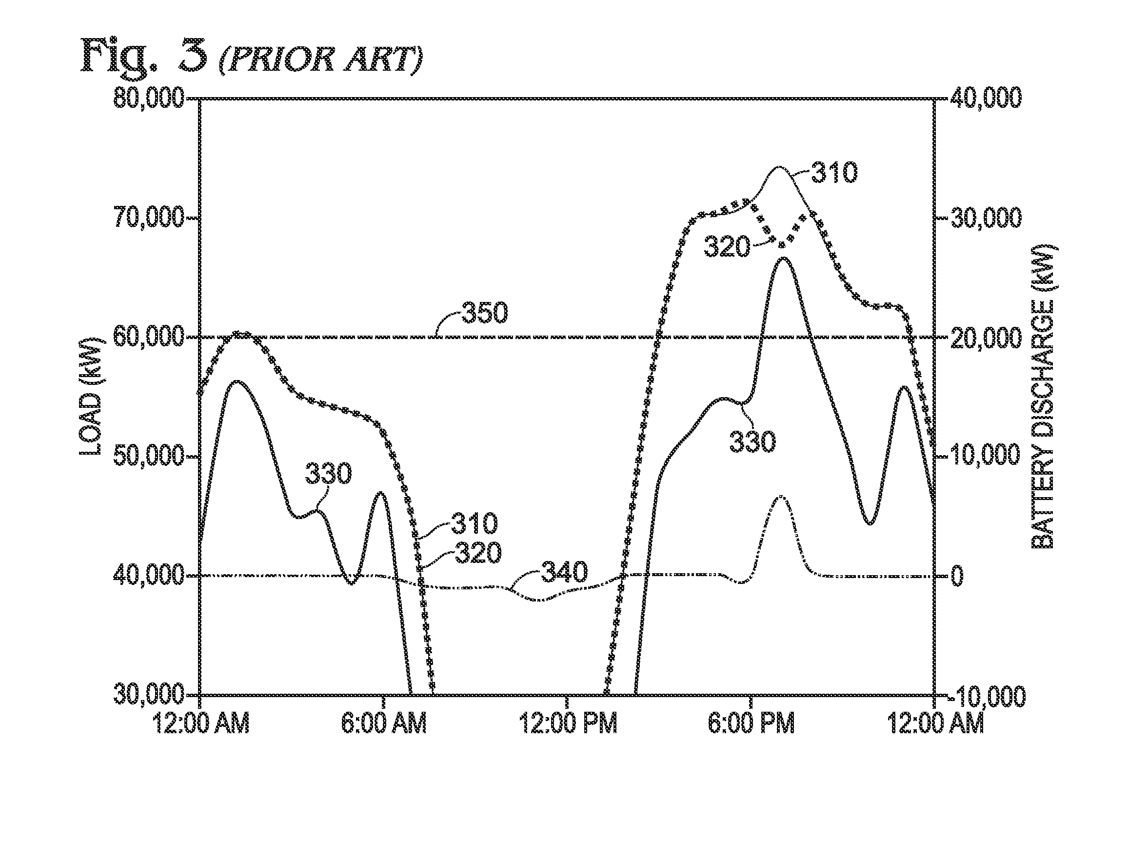
However, due to failure to account for all power consumed at the site, the management system sees an erroneous actual load 330 that grossly underestimates true actual load 310.
Such a failure might result from malfunction of a meter that measures power consumption at the site or a communications channel between such a meter and a peak load management controller.
In other examples, a catastrophic failure in determining actual load at the site may occur that prevents the peak load management system from making an even remotely informed decision about when to discharge battery power.
In any of these circumstances, the lack of accurate data on actual load at the site can quickly decimate the cost savings that would otherwise be achieved by the peak load management system.

Method used


Image

  • Method and System for Mitigating Impact of Malfunction in Actual Load Determination on Peak Load Management
  • Method and System for Mitigating Impact of Malfunction in Actual Load Determination on Peak Load Management
  • Method and System for Mitigating Impact of Malfunction in Actual Load Determination on Peak Load Management

Examples


Embodiment Construction

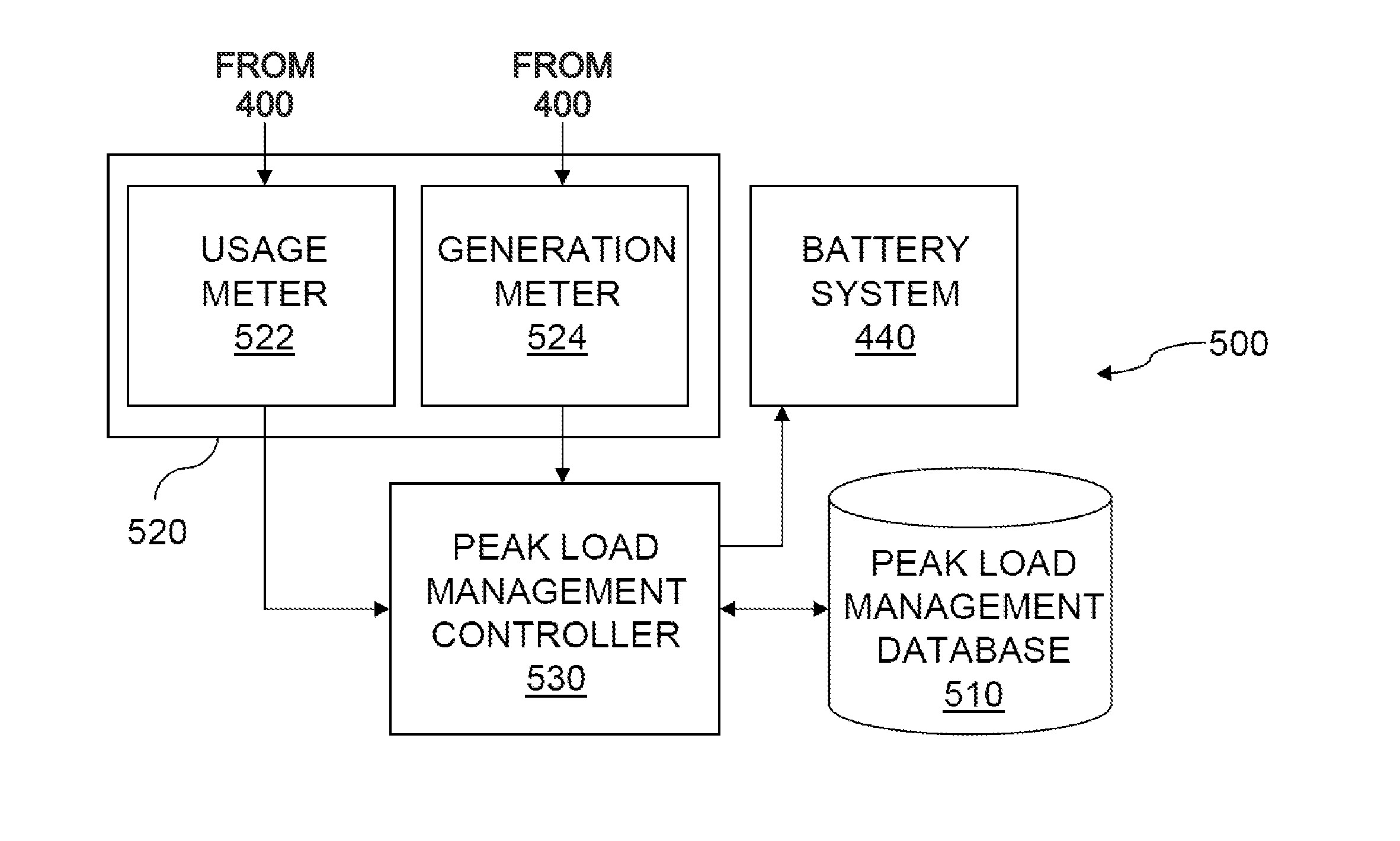
[0033]FIG. 4 shows a power system 400 for a site 410 operated by a site owner who is a customer of an electric utility. Power system 400 includes multiple power sources that supply power to site 410 at various times and in various amounts. The power sources include a grid power supply 420 drawn on the electric utility. The electric utility that supplies the grid power bills the site owner periodically, such as monthly, for grid power. These periodic electric utility bills include a peak load component that assesses the site owner a charge based on the peak usage of grid power at site 410 during the billing period. The power sources also include a solar generator 430 that supplies power to site 410 during daylight hours, at least partially offsetting the use of grid power. Moreover, the power sources include a battery system 440 that, under control of a peak load management system 500, discharges stored power as needed to cap the usage of grid power at a target peak load, which caps ...


PUM


Abstract

Method and system for mitigating the impact on peak load management of a malfunction in determining actual load at a site by substituting a predicted load for actual load while the malfunction persists. Using a predicted load as a substitute for actual load during the malfunction period avoids use of a grossly overestimated or underestimated actual load that if used could cause suboptimal use of battery power and decimate cost savings from peak load management.

Description

BACKGROUND OF THE INVENTION[0001]The present invention relates to power management and, more particularly, to managing the peak load drawn by a site owner on an electric utility to reduce the site owner's utility bills.[0002]Utility bills often include a peak load component that assesses a site owner a charge based on the peak usage of grid power at the site during a multi-day billing period. The multi-day billing period is typically about 30 days, but may be up to a year. The peak load is typically assessed as the maximum average load in any 30 or 60 minute period within the multi-day billing period.[0003]To reduce the amount of the peak load charge, it is known to deploy a peak load management system that continually measures load at the site throughout the billing period and limits the use of grid power to a target peak load. The target peak load is often statically configured for the billing period, either manually or by an algorithm running on the management system.[0004]FIG. 1...

Claims


Application Information

Patent Timeline
Patent Type & Authority Applications(United States)
IPC IPC(8): G06F1/26
CPCH02J3/32H02J2310/12H02J2300/24H02J3/381Y02E10/56Y02E70/30Y02P80/14
Inventor MANSFIELD, CARL
Owner NANTENERGY INC
Learn More