Supercharge Your Innovation With Domain-Expert AI Agents!

Seat pad and seat for vehicle

a seat pad and vehicle technology, applied in the direction of vehicle components, chairs, vehicle arrangements, etc., can solve the problems of insatiable improvement of soft touch, high cost of foam molding by using materials of different types, and inability to achieve good sitting comfort, improve the soft touch sensation, and improve the comfort of sitting

Active Publication Date: 2013-12-12
ARCHEM INC
View PDF9 Cites 4 Cited by
  • Summary
  • Abstract
  • Description
  • Claims
  • Application Information

AI Technical Summary

Benefits of technology

The seat pad for a vehicle described in this patent provides improved touch sensation and comfort for the occupant through the use of recessed holes and ridge portions. The recessed holes have ridge portions that compress and deform when the occupant touches the surface, providing a soft sensation of touch. The ridge portions are continuously present in multiple directions, and are designed to buckle when significantly compression-deformed, ensuring good sitting comfort. The seat pad also maintains a soft sensation of touch through the use of shallow recessed holes and ridge portions, as well as specific depth and area ranges. Additionally, by providing ridge portions in two intersecting directions, the mold design is simplified, and poor sitting comfort due to incorrect ridge portion extending direction is less likely to occur.

Problems solved by technology

However, effecting foam molding by using materials of different types is costly.
However, pasting a slab on a pad main body is costly.
When buttocks and / or thighs of an occupant are in contact with the pad surface, the aforementioned slits of the pad surface hardly contribute to the occupant's feeling soft sensation of touch and thus improvement of soft sensation of touch is not satisfactory.

Method used


Image

  • Seat pad and seat for vehicle
  • Seat pad and seat for vehicle
  • Seat pad and seat for vehicle

Examples


examples

[0186]Examples and Comparative Examples will be described hereinafter. For convenience, Comparative Example 1 will be described first.

example 1

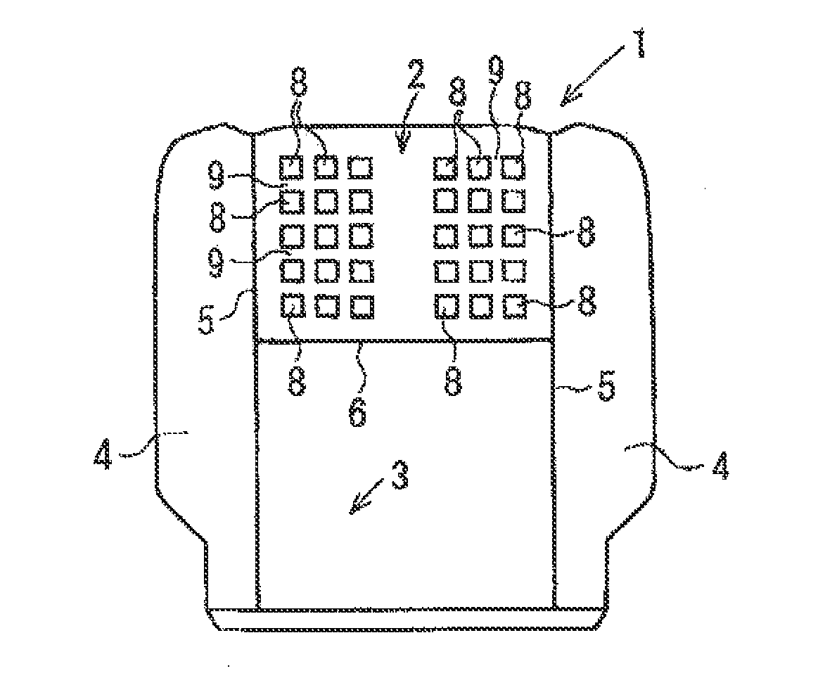
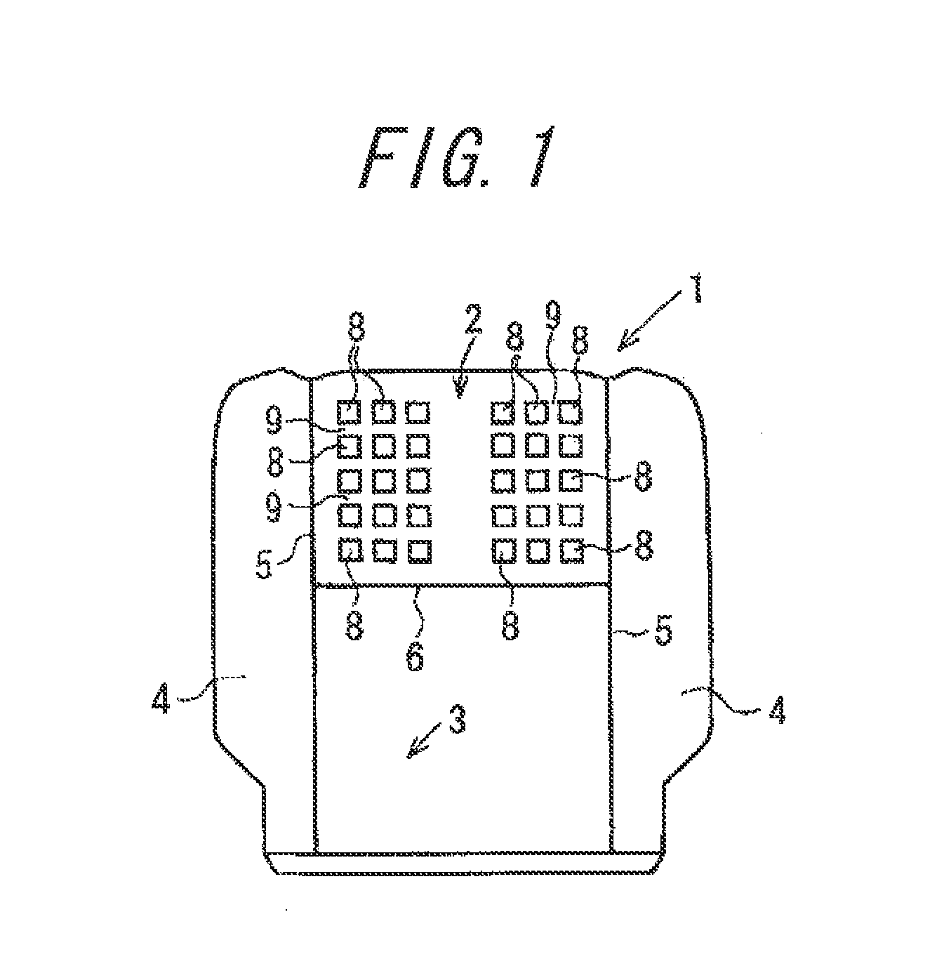
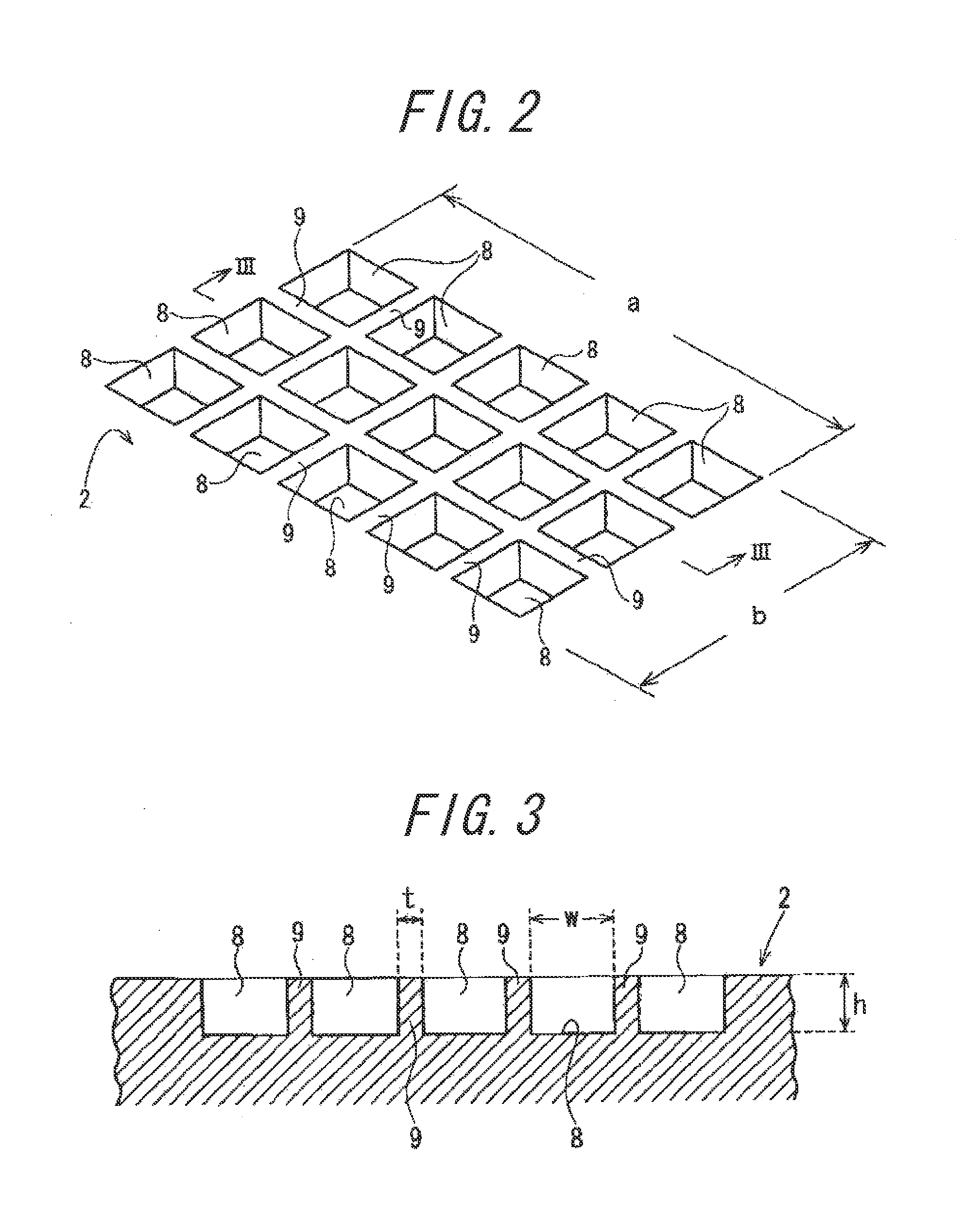
[0188]A seat pad as shown in FIGS. 1 to 3 was produced by providing projecting portions in a surface (a cavity surface) for molding an under-thighs portion of a mold for use in molding of Comparative Example 1 and using the same urethane raw liquid as Comparative Example 1. The dimensions of w, t and h are 20 mm, 4 mm and 10 mm, respectively. The volume rate of the ridge portions 9 in Example 1 is 33.3%. The density and the 25% hardness of polyurethane are 64 kg / cm3 and 19 kgf / 200 mmφ, respectively. A load applying means was pressed against the under-thighs portion of the seat pad in a manner similar to Comparative Example 1 and a load-stroke curve was obtained. The result is shown in FIG. 22.

example 2

[0195]A seat pad as shown in FIGS. 1 to 3 was prepared by setting: the dimensions w, t and h at 26 mm, 4 mm and 10 mm, respectively; the ratio of areas of the ridge portions 9 in the total areas of the recessed holes 8 and the ridge portions 9 at 25%; the volume rate of the ridge portions 9 at 25%; and the density and the 25% hardness at 64 kg / cm3 and 18 kgf / 200 mmφ, respectively. A load applying means was pressed against the seat pad in a manner similar to Comparative Example 1 and a load-stroke curve was obtained. The result is shown in FIG. 23.


PUM


Abstract

Ridge portions 9 are provided to be continuously present in orthogonally intersecting directions by forming plural recessed holes 8 in the upper surface of an under-thighs portion 2 and an under-buttocks portion 3 of a seat pad 1 for a vehicle. The height of each ridge portion 9, i.e. the depth h of each recessed hole 8, is preferably in the range of 2 to 40 mm, more preferably in the range of 5 to 20 mm, the width w of each recessed hole 8 is preferably in the range of 10 to 30 mm, more preferably in the range of 20 to 30 mm, and the area of an opening of each recessed hole 8 is preferably in the range of 50 to 1000 mm2, more preferably in the range of 100 to 900 mm2. Accordingly, the present invention can provide a seat pad, which is excellent in soft sensation of touch of a surface thereof, satisfactory in the properties of supporting an occupant, and can be produced by integral foam molding.

Description

CROSS REFERENCE TO RELATED APPLICATIONS[0001]This application is a divisional of U.S. application Ser. No. 12 / 670,307, filed Mar. 1, 2010, which is a National Stage of International Application No. PCT / JP2008 / 063214, filed on Jul. 23, 2008, which claims priority from Japanese Patent Application No. 2007-190967, filed Jul. 23, 2007, Japanese Patent Application No. 2007-323520, filed Dec. 14, 2007 and Japanese Patent Application No. 2008-155503, filed Jun. 13, 2008, the contents of all of which are incorporated herein by reference in their entirety.TECHNICAL FIELD[0002]The present invention relates to a seat pad for a vehicle and a seat for a vehicle and, in particular, to a seat pad for a vehicle and a seat for a vehicle each having a passenger contact surface made to have soft sensation of touch or good sensation of the pad making a stroke movement.PRIOR ART[0003]A seat pad mounted to a vehicle seat or the like is conventionally manufactured by pouring an urethane blend raw liquid p...

Claims


Application Information

Patent Timeline
Patent Type & Authority Applications(United States)
IPC IPC(8): B60N2/64B60N2/90
CPCB60N2/646B60N2/01508B60N2/3097
Inventor HIRATA, YUTAKAOKUMURA, MASANORIYONEZAWA, TAISUKE
Owner ARCHEM INC
Features
  • R&D
  • Intellectual Property
  • Life Sciences
  • Materials
  • Tech Scout
  • Unparalleled Data Quality
  • Higher Quality Content
  • 60% Fewer Hallucinations
Learn More