Handheld antenna attitude measuring system

a technology of attitude measurement and antenna, which is applied in the direction of measurement devices, instruments, satellite radio beaconing, etc., can solve the problems of inability to continuously monitor the orientation of the antenna and detect the disorientation from a baseline orientation, the inability of cellular telecommunications antennas to be susceptible to physical disorientation, and the degradation of communications performance, so as to achieve maximum network performance

Inactive Publication Date: 2013-12-12
LE SAGE HENDRIKUS A
View PDF2 Cites 12 Cited by
  • Summary
  • Abstract
  • Description
  • Claims
  • Application Information

AI Technical Summary

Benefits of technology

[0010]In a handheld antenna attitude measuring system embodying the principles of the present invention, data from internal and external antenna electrical components are recorded and displayed on a handheld device, and transmitted to a database accessed by a network operator. Accumulating and displaying the data in a handheld device enables a site technician to adjust the attitude of the antenna in real time; transmission and recordation of the data to a separate database enables a network operator to utilize the antenna attitude data to maximize network performance.

Problems solved by technology

A significant disadvantage associated with previous antenna orientation and adjustment devices and methods involve their inability to continuously monitor antenna orientation and detect disorientation from a baseline orientation.
Cellular telecommunications antennas are susceptible to physical disorientation from various causes, such as meteorological, geological, and other impact forces.
For example, forces generated during a major storm may change the orientation of antenna housings on telecommunications towers and in other installations within an entire region resulting in communications performance degradation.
Therefore, an antenna orientation and adjustment system and method should not only facilitate initial orientation, but also facilitate ongoing orientation monitoring with an ability to detect conditions of disorientation, thereby requiring limited physical visits by technicians to antenna installations, and limited need for specialized equipment in order to effectuate installation and orientation of telecommunications antenna.

Method used


Image

  • Handheld antenna attitude measuring system
  • Handheld antenna attitude measuring system
  • Handheld antenna attitude measuring system

Examples


Embodiment Construction

I. Introduction and Environment

[0020]As required, detailed aspects of the present invention are disclosed herein; however, it is to be understood that the disclosed aspects are merely exemplary of the invention, which may be embodied in various forms. Therefore, specific structural and functional details disclosed herein are not to be interpreted as limiting, but merely as a basis for the claims and as a representative basis for teaching one skilled in the art how to variously employ the present invention in virtually any appropriately detailed structure.

[0021]Certain terminology will be used in the following description for convenience in reference only and will not be limiting. Said terminology will include the words specifically mentioned, derivatives thereof and words of similar meaning

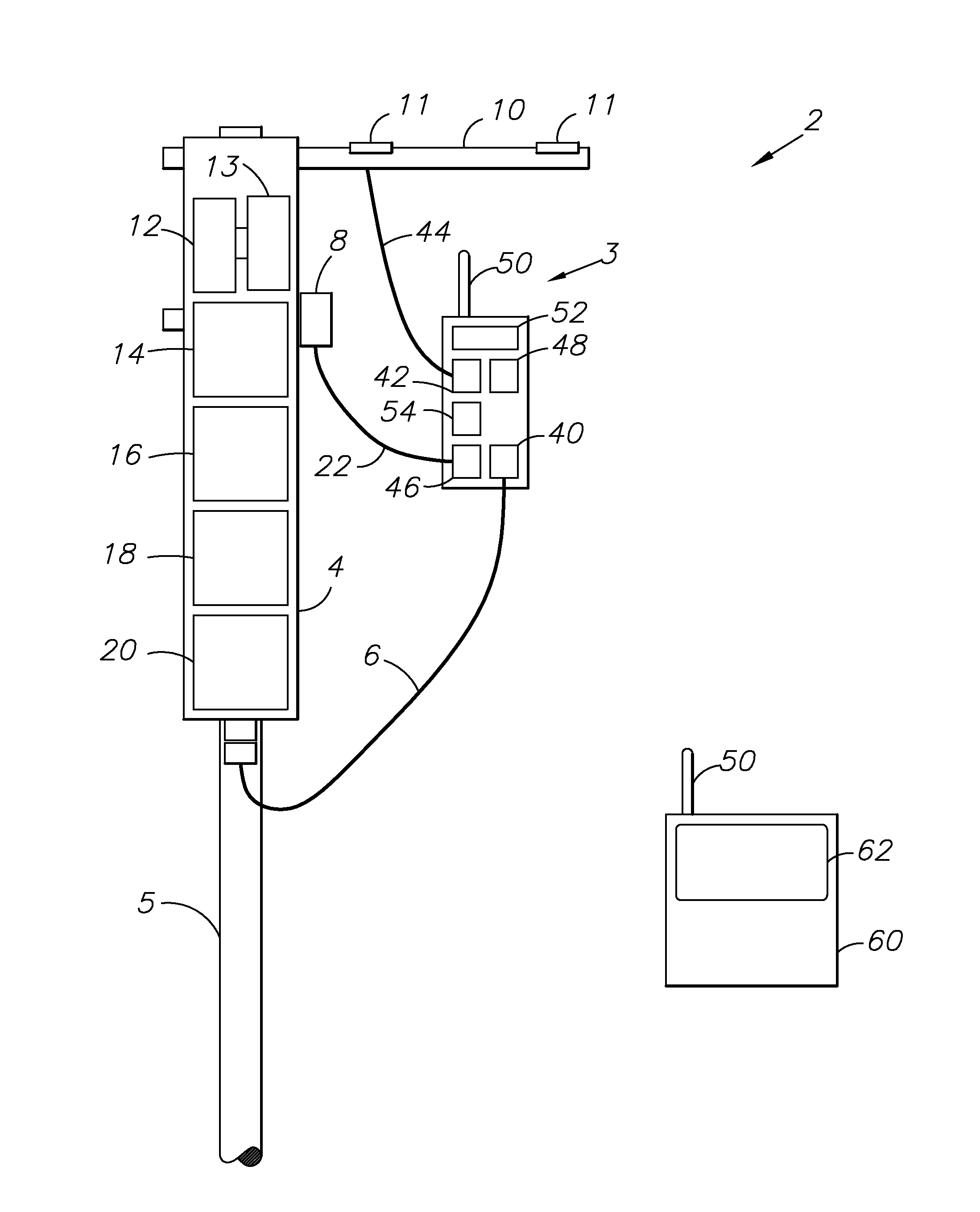
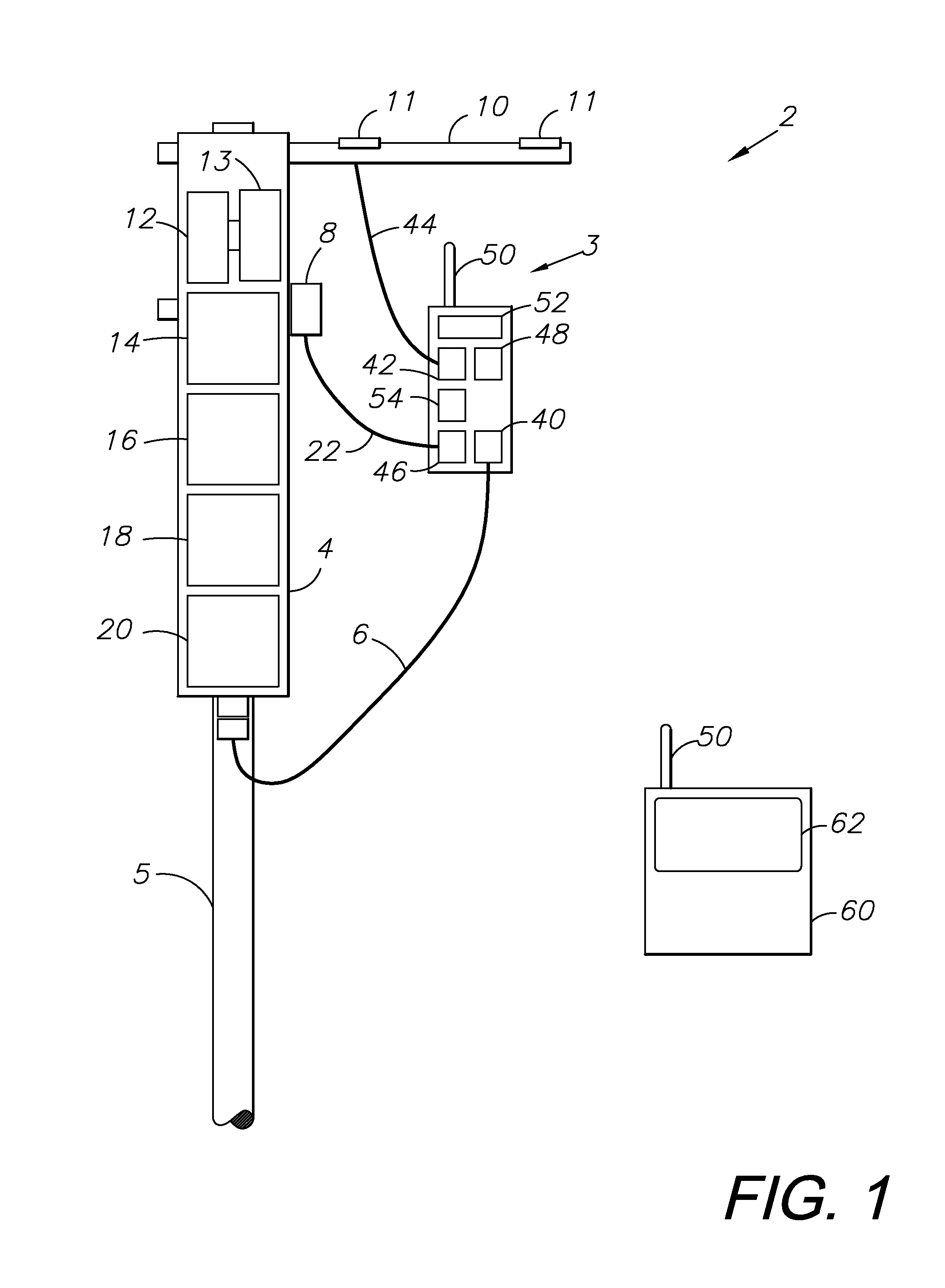
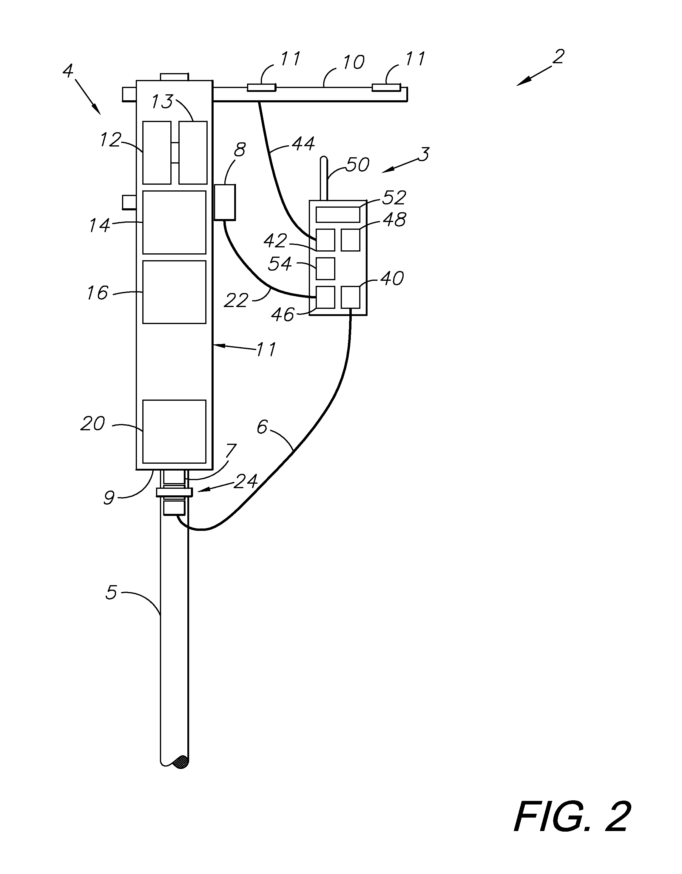
II. Preferred Embodiment Attitude Measuring System 2

[0022]Referring to the drawings in more detail, the reference numeral 2 generally designates a handheld antenna attitude measuring system embody...


PUM


Abstract

An antenna attitude measuring system includes internal and external electrical components providing data for recording and displaying on a handheld device. The data can be transmitted to a database for access by a network operator. The antenna attitude can be adjusted for maximizing telecommunications network performance. The system includes an AISG compliant tilt sensor system mounted in-line between a telecommunications antenna enclosure and a communications cable, and positioned to measure the elevation tilt and slant of a telecommunications antenna enclosure relative to a reference axis. The system includes the ability to connect to and remotely control a plurality of remote electrical tilt control units through only a single connection.

Description

CROSS-REFERENCE TO RELATED APPLICATIONS[0001]This application is a continuation-in-part of and claims the benefit of U.S. patent application Ser. No. 12 / 947,658 filed Nov. 16, 2010, which claims the benefit of U.S. Provisional Application No. 61 / 261,459, filed Nov. 16, 2009, and is also a continuation-in-part of U.S. patent application Ser. No. 12 / 816,150 filed Jun. 15, 2010, which claims the benefit of U.S. Provisional Application No. 61 / 187,129 filed on Jun. 15, 2009.BACKGROUND OF THE INVENTION[0002]1. Field of the Invention[0003]The present invention relates generally to antenna orientation and measurements, and in particular to a system for measuring, recording, and transmitting cellular telecommunications antenna attitude data using a remote element.[0004]2. Description of the Related Art[0005]Telecommunication antennas require precise installation and orientation to function efficiently. The physical parameters that affect antenna performance include azimuth, elevation tilt, a...

Claims


Application Information

Patent Timeline
Patent Type & Authority Applications(United States)
IPC IPC(8): G01S19/53
CPCG01S19/53G01S19/14H01Q1/125H01Q1/246
Inventor LE SAGE, HENDRIKUS A.
Owner LE SAGE HENDRIKUS A
Why Eureka
Try Eureka