Head mount display

a display and head mount technology, applied in the field of head mount displays, can solve the problems of affecting the upper end of the ear lobes over which the end covers of the temples are placed, and the display can not be used for a long time,

Inactive Publication Date: 2013-12-19
SONY CORP
View PDF4 Cites 25 Cited by
  • Summary
  • Abstract
  • Description
  • Claims
  • Application Information

AI Technical Summary

Benefits of technology

[0017]According to the present invention, an excellent head mount display capable of being worn around the head while being adjusted according to an increase in the entire weight of the device and an individual difference in the size of the head or the like of each user can be provided.
[0018]The head mount display according to the present invention has a mechanism to be worn around the head of a user with a three-point support by a forehead support, a lower band and an upper band, and can be worn without making the user notice the loads. Furthermore, since a mechanism for adjusting the entire length of a headband having the upper band and the lower band is provided and a mechanism for adjusting the height of the forehead support is further provided, adjustment to a wide variety of individual differences in the size of the head of the user is possible.

Problems solved by technology

Since, however, a head mount display typically has heavy loads such as display units including optical components made of glass materials and an electric circuit board concentrated on a body at the front, the head mount display can hardly be used for a long time by the way of wearing instructed by a nosepiece and left and right temples as described above owing to excessive loads applied to the nose of the user.
Obviously, upper ends of ear lobes over which the end covers of the temples are placed will hurt.

Method used


Image

  • Head mount display
  • Head mount display
  • Head mount display

Examples


Embodiment Construction

[0035]An embodiment of the present invention will be described in detail below with reference to the drawings.

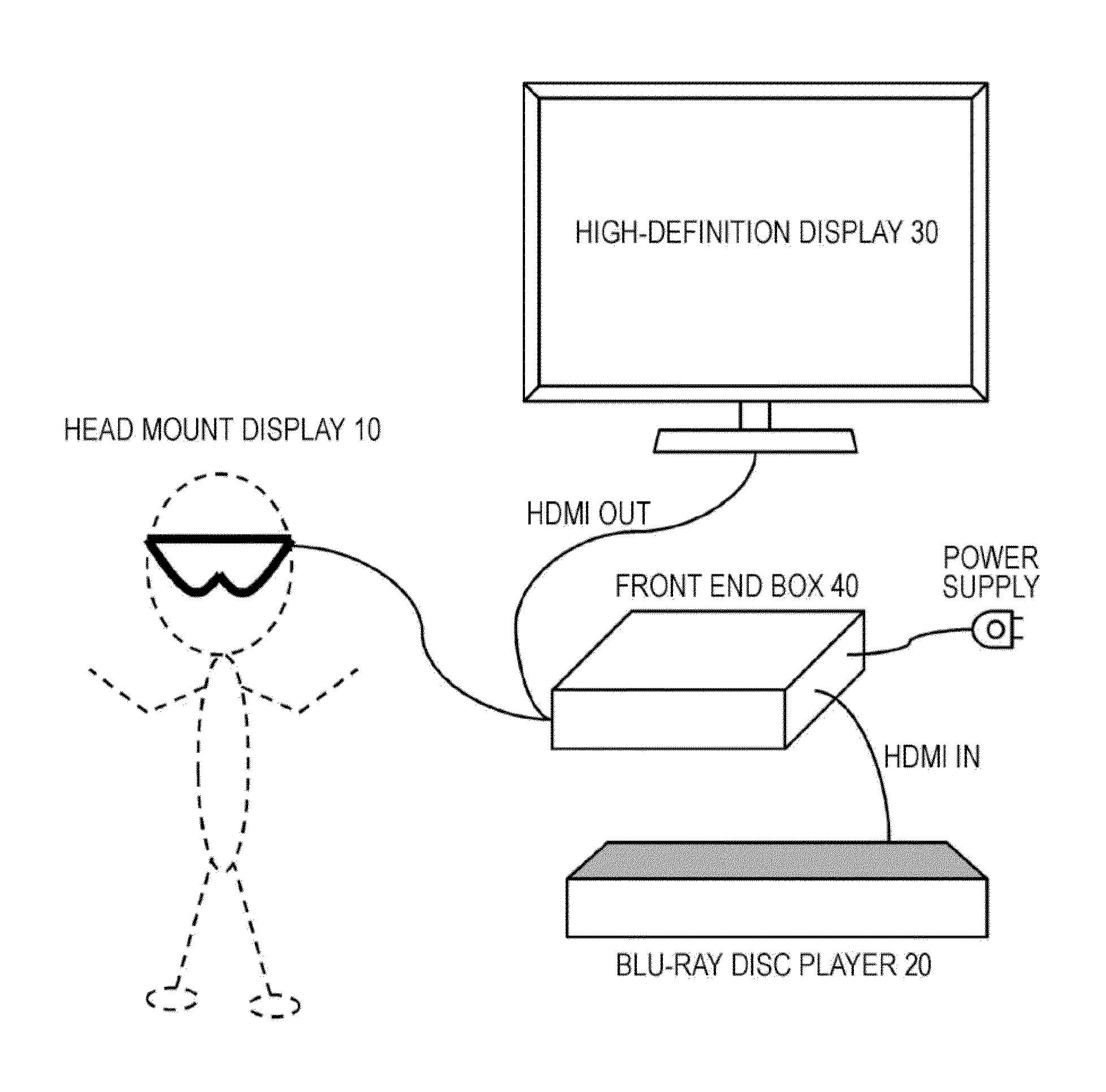
[0036]FIG. 10 shows a configuration of an image display system including a head mount display. The shown system includes a body of a head mount display 10, a Blu-ray disc player 20 that is a source of contents to be viewed, a high-definition display (an HDMI-compatible television, for example) 30 to which contents reproduced by the Blu-ray disc player 20 are output, and a front end box 40 that processes AV signals output from the Blu-ray disc player 20.

[0037]The front end box 40 corresponds to an HDMI repeater that processes an AV signal output from the Blu-ray disc player 20 and input in HDMI and outputs the signal in HDMI, for example. The front end box 40 is also a two output switcher that switches the output of the Blu-ray disc player 20 between the head mount display 10 and the high-definition display 30.

[0038]While the front end box 40 has two outputs in the shown exam...


PUM


Abstract

A head mount display used in a state worn on the head of a user is provided.In a worn state, a forehead support 102 comes in contact with the forehead of the user, and an upper band 104 and a lower band 105 of the headband come in contact with the back of the head. That is, the head mount display is worn on the head of the user with a three-point support by the forehead support 102, the upper band 104, and the lower band 105. Thus, unlike a structure similar to glasses whose weight is mainly supported by a nose piece, the head mount display can be worn while easing the strain on the user by distributing the load of the device over the entire head.

Description

TECHNICAL FIELD[0001]The present invention relates to a head mount display used in a state worn around the head of a user, and in particular to a head mount display worn around the head while being adjusted according to an increase in the entire weight of the device and an individual difference in the size of the head or the like of each user.BACKGROUND ART[0002]Display devices to be worn around the head to view video, that is, head mount displays (HMD) have been widely known. A head mount display includes a display unit for each of left and right eyes, and is combined with a headphone and configured to be capable of visual and audio control. A configuration to perfectly shut out the outside world while being worn around the head increases virtual reality during viewing. Furthermore, a head mount display is also capable of showing different pictures to the left and right eyes, and can present three-dimensional images by displaying images with a parallax for the left and right eyes.[...

Claims


Application Information

Patent Timeline
Patent Type & Authority Applications(United States)
IPC IPC(8): H04N13/04
CPCH04N13/044G02B27/0176H04N2213/001H04N2213/008H04N13/344
Inventor KURA, JUMPEIMITSUI, TAKEOSAKAGUCHI, MASAYUKI
Owner SONY CORP
Why Eureka
Try Eureka