Image forming apparatus

a technology of image forming apparatus and forming roller, which is applied in the direction of electrographic process apparatus, instruments, optics, etc., can solve the problems of contaminating the transfer roller, defective image, and image defect in the next image formation, and achieve the effect of suppressing an image d

Active Publication Date: 2013-12-19
CANON KK
View PDF23 Cites 4 Cited by
  • Summary
  • Abstract
  • Description
  • Claims
  • Application Information

AI Technical Summary

Benefits of technology

[0008]The present invention has been made to suppress an image defect due to a failure in removing a developer by a cleaning unit.

Problems solved by technology

At this time, if a voltage having the same polarity as that of the voltage applied in the image forming operation is applied to the transfer roller, the toner on the photosensitive drum is transferred to the transfer roller, and contaminates the transfer roller.
Thus, an image defect may occur in the next image formation.
In such a case, the toner that cannot be completely removed and slips through the cleaning blade is adhered to the charging roller, causing a charging failure, which may generate a defective image such as a streaky image.
In addition, the toner that has slipped through the cleaning blade may be printed in the next image formation after the recovery operation, causing an image defect such as a streak on an image.

Method used


Image

  • Image forming apparatus
  • Image forming apparatus
  • Image forming apparatus

Examples


first embodiment

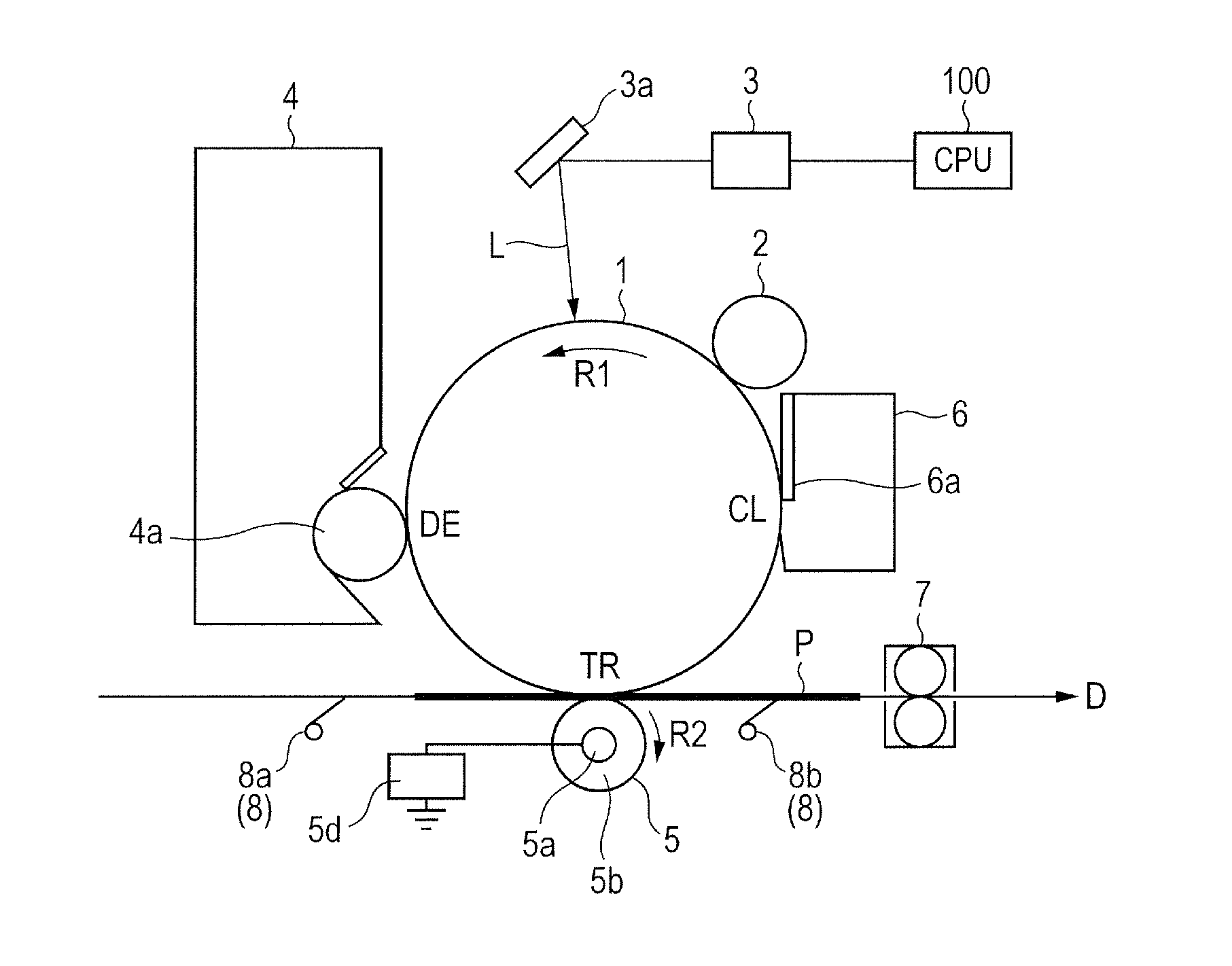
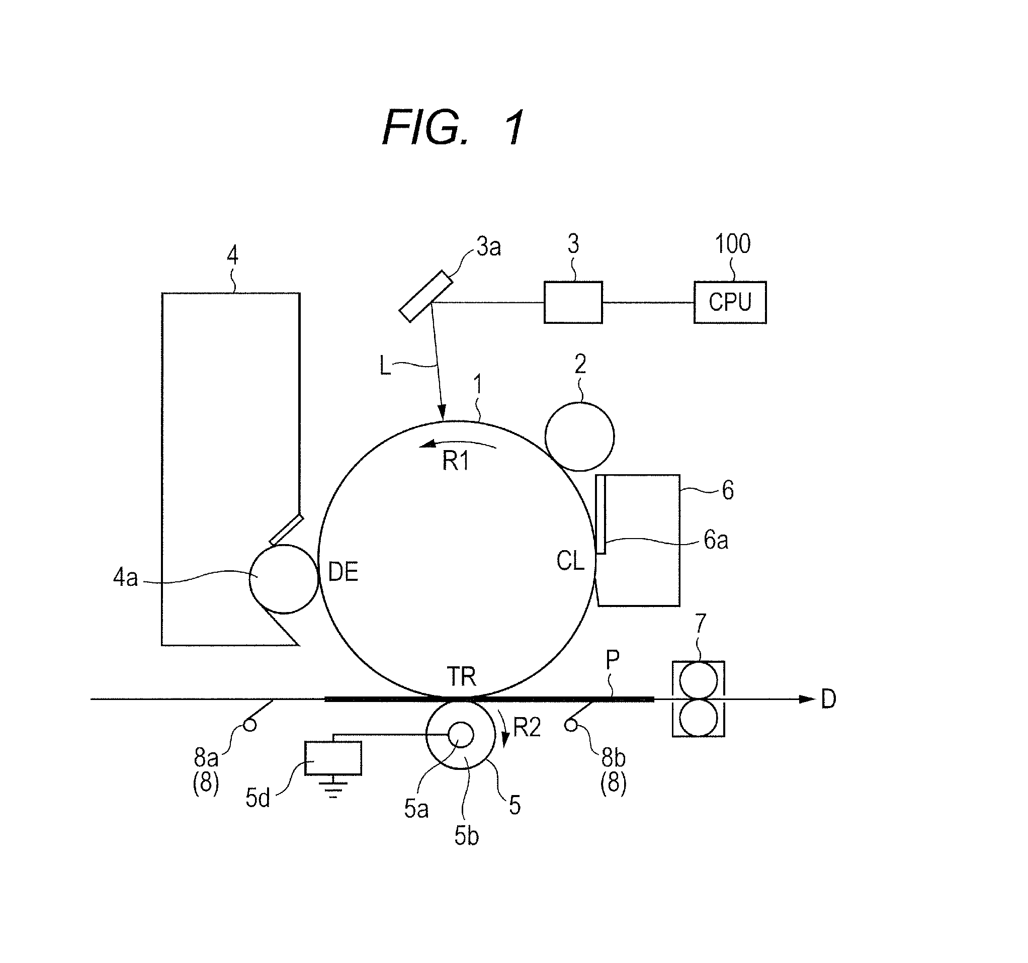
[0021]The photosensitive drum 1 is rotatably provided to receive a driving force at the time of performing an image forming operation and to rotate in a direction indicated by an arrow R1 in FIG. 1 at a predetermined process speed (rotation speed). In the present invention, a diameter of the photosensitive drum 1 is 24 mm and the rotation speed is 100 mm / sec.

[0022]The charging roller 2 is provided so as to abut against the photosensitive drum 1 and uniformly charges a surface of the photosensitive drum 1. The charging roller is arranged upstream of the developing device 4 in a rotation direction of the photosensitive drum 1. The exposing device 3 emits a laser beam L to expose the surface of the photosensitive drum 1 via a reflection mirror 3a.

[0023]The developing device 4 includes a developing roller 4a as a developing unit, which is rotatably provided. The developing roller 4a carries a toner as a developer on its surface, and supplies the toner to the photosensitive drum 1. In t...

experiment 1

[0049 will be described first. In the process of Step SS2 illustrated in FIG. 3, when the voltage V1 was set to +1,500 V, the amount of the toner transferred to the transfer roller 5 was 95%. That is, the amount of the toner conveyed to the cleaning blade 6a was 5%, which did not cause any slip-through of the toner. Further, in the process of Step SS3 illustrated in FIG. 3, when the voltage V2 was set to −1,500 V, the amount of the toner transferred to the transfer roller 5 and then transferred from the transfer roller 5 again to the photosensitive drum 1 was 90%. That is, the amount of the toner conveyed to the cleaning blade 6a was more than 50%, which caused the slip-through of the toner.

[0050]In Experiment 2, the voltage V1 in the process of Step SS2 illustrated in FIG. 3 was set to +1,500 V in the same manner as in Experiment 1, and the voltage V2 in the process of Step SS3 illustrated in FIG. 3 was set to −1,200 V. In this case, the amount of the toner transferred to the trans...


PUM


Abstract

An image forming apparatus, including: a rotatable image bearing member; a developing unit configured to supply a developer onto the image bearing member; a transfer unit configured to transfer the developer on the image bearing member to a recording medium by a transfer voltage being applied to the transfer unit by a voltage applying unit; and a cleaning unit configured to remove the developer on the image bearing member, wherein when the apparatus stops an image forming operation halfway, the apparatus executes a recovery operation in which the image bearing member is rotated while the voltage applying unit applies a voltage to the transfer unit so that a part of the developer remaining on the image bearing member is once transferred from the image bearing member to the transfer unit, transferred again from the transfer unit to the image bearing member, and then removed by the cleaning unit.

Description

BACKGROUND OF THE INVENTION[0001]1. Field of the Invention[0002]The present invention relates to an image forming apparatus.[0003]2. Description of the Related Art[0004]An image forming apparatus such as a laser beam printer includes a photosensitive drum as an image bearing member, a transfer roller as a transfer unit, and a cleaning blade as a cleaning unit. At the time of performing an image forming operation, a predetermined transfer voltage is applied to the transfer roller in order to transfer a toner as a developer on the photosensitive drum to a recording medium such as paper.[0005]There is known such a configuration that, when the image forming operation is stopped halfway due to a generation of a paper jam or the like, a recovery operation is performed before resuming the image forming operation, to thereby remove the toner remaining on the photosensitive drum without being transferred to the recording medium. The removal of the toner remaining without being transferred is...

Claims


Application Information

Patent Timeline
Patent Type & Authority Applications(United States)
IPC IPC(8): G03G15/16
CPCG03G21/0005G03G21/0011G03G15/161G03G15/0189
Inventor IKEDA, TAKAHIROISOBE, YUTAMIZUKOSHI, SHUNSUKETETSUNO, SHUICHIKANAI, RYOSUKE
Owner CANON KK
Why Eureka
Try Eureka