Pipe Handling Apparatus and Method

a technology for handling equipment and pipes, applied in the oil and gas industry, can solve the problems of difficult to move the pipe from a horizontal position on the pipe rack to a vertical position, the weight of the pipe joints is thousands of pounds, and the handling of oil well pipes is one of the most dangerous jobs on the drilling rig

Active Publication Date: 2013-12-19
AXIS ENERGY SERVICES LLC
View PDF13 Cites 26 Cited by
  • Summary
  • Abstract
  • Description
  • Claims
  • Application Information

AI Technical Summary

Benefits of technology

[0010]It is another object of the present invention to provide a pipe handling apparatus and method that facilitates movement of elongated tubular member, such as pipe segments, from a horizontal rack to platform floor and back to the pipe rack.

Problems solved by technology

The handling of oil well pipe is one of the most dangerous jobs on a drilling rig.
Some of the pipe joints weigh thousands of pounds, and it is difficult to move the pipe from a horizontal position on the pipe rack into a vertical position overlying the borehole in the rig.

Method used


Image

  • Pipe Handling Apparatus and Method
  • Pipe Handling Apparatus and Method
  • Pipe Handling Apparatus and Method

Examples


Embodiment Construction

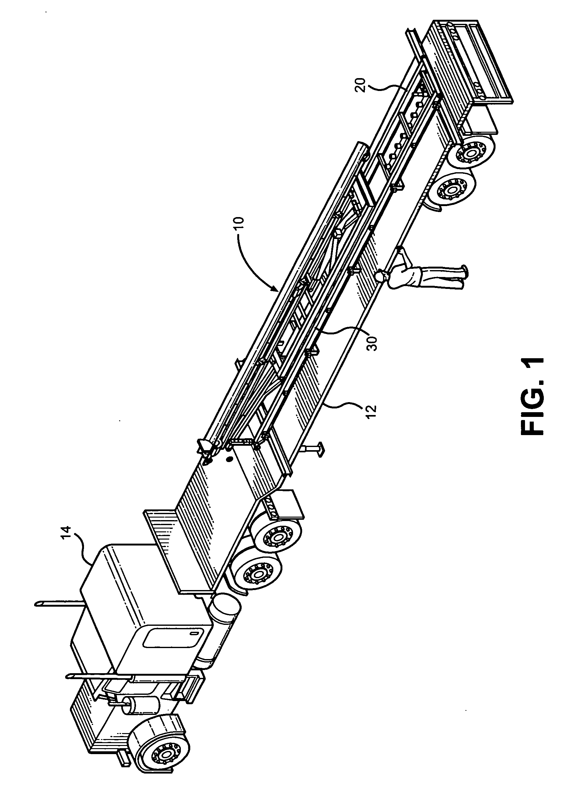
[0054]Turning now to the drawings in more detail, numeral 10 designates the pipe handling apparatus according to this invention. The apparatus 10 can be delivered to a work site in any available manner, for instance a trailer 12 illustrated in FIG. 1. The trailer 12 can be attached to a towing vehicle 14 and transported to the designated location, such as a site of a drilling rig 16.

[0055]The apparatus 10 comprises a base, such as a skid 20, which supports the apparatus 10 in a longitudinal position during transport. The skid 20 can be formed as an open frame composed of a pair of parallel rails 22, 24 and a plurality of transverse bars 26 extending between the opposing rails 22, 24. The skid 20 can be positioned on the ground adjacent a storage rack 18 and the drilling rig 16 and moved to a pre-selected position using rotating skid wheels 28 secured to ends of the elongated rails 22, 24. The rails 22 and 24 can be formed as elongated I-beams in cross-section.

[0056]Since the skid 20...


PUM


Abstract

Equipment for moving tubular members from a storage rack to an elevated platform floor is disclosed. A base-mounted articulated support structure has an arcuate trough mounted on top thereof. Loading arms are secured to a side of the pivotal trough for picking up one tubular member from the rack and moving to the platform floor. Unloading arms detachably securable to the trough facilitate movement of the tubular members from the platform floor onto the rack. A plurality of roller sets mounted between the base and the trough supporting structure move the trough along the base for easy reach to the platform floor.

Description

CROSS-REFERENCE TO RELATED APPLICATIONS[0001]This application is a continuation-in-part of my co-pending application Ser. No. 13 / 523,238 Filed on Jun. 14, 2012 entitled “Pipe Handling Apparatus and Method,” the full disclosure of which is incorporated by reference herein and priority of which is hereby claimed.BACKGROUND OF THE INVENTION[0002]This invention relates to oil and gas industry and, more particularly to an apparatus for moving elongated tubular members between a rack and a rig floor.[0003]During drilling and completion operations, it is necessary to make up and / or break down long strings of tubular members such as drill pipe and casing. The string of pipe may be thousands of feet long, and it is therefore necessary to transport pipe joints, which can be up to 32 feet long, from a pipe rack located away from the rig up to the rig floor. When the drill string is tripped out of the hole, the string of pipe is broken down into separate joints and returned to the pipe rack. Th...

Claims


Application Information

Patent Timeline
Patent Type & Authority Applications(United States)
IPC IPC(8): E21B19/14E21B19/15
CPCE21B19/14E21B19/155
Inventor HILTON, THOMAS DALE
Owner AXIS ENERGY SERVICES LLC
Why Eureka
Try Eureka