Structural Representation and Facilitation of Manipulation Thereof Via Implicit Vertex Relationships

a technology of vertex relationships and structural representation, applied in the direction of walls, manufacturing tools, instruments, etc., can solve the problems of incongruity, inability to reproduce and/or trace features between levels, and inability to achieve the effect of facilitating manipulation

Active Publication Date: 2013-12-19
HERE GLOBAL BV
View PDF23 Cites 6 Cited by
  • Summary
  • Abstract
  • Description
  • Claims
  • Application Information

AI Technical Summary

Problems solved by technology

While these techniques are straightforward and may result in highly accurate representations of a structure or space, they also suffer from problems.
For example, the copying and/or tracing of features between levels can propagate and/or exaggerate design errors such as offsets between features which should be collinear among levels.
Such errors may be introduced due to user error and/or due to imprecision in the representation of features, such as on a display screen, as compared with the actual characteristics of the actual physical features.
For example, when manipulating, such as scaling or translating, the floor plan of multiple levels for the purpose of creating a derivation thereof, e.g. navigational maps of the interior space, these errors may be revealed as incongruities between the levels and misrepresentations of relationships between locations.
Rubber-sheeting...

Method used


Image

  • Structural Representation and Facilitation of Manipulation Thereof Via Implicit Vertex Relationships
  • Structural Representation and Facilitation of Manipulation Thereof Via Implicit Vertex Relationships
  • Structural Representation and Facilitation of Manipulation Thereof Via Implicit Vertex Relationships

Examples


Embodiment Construction

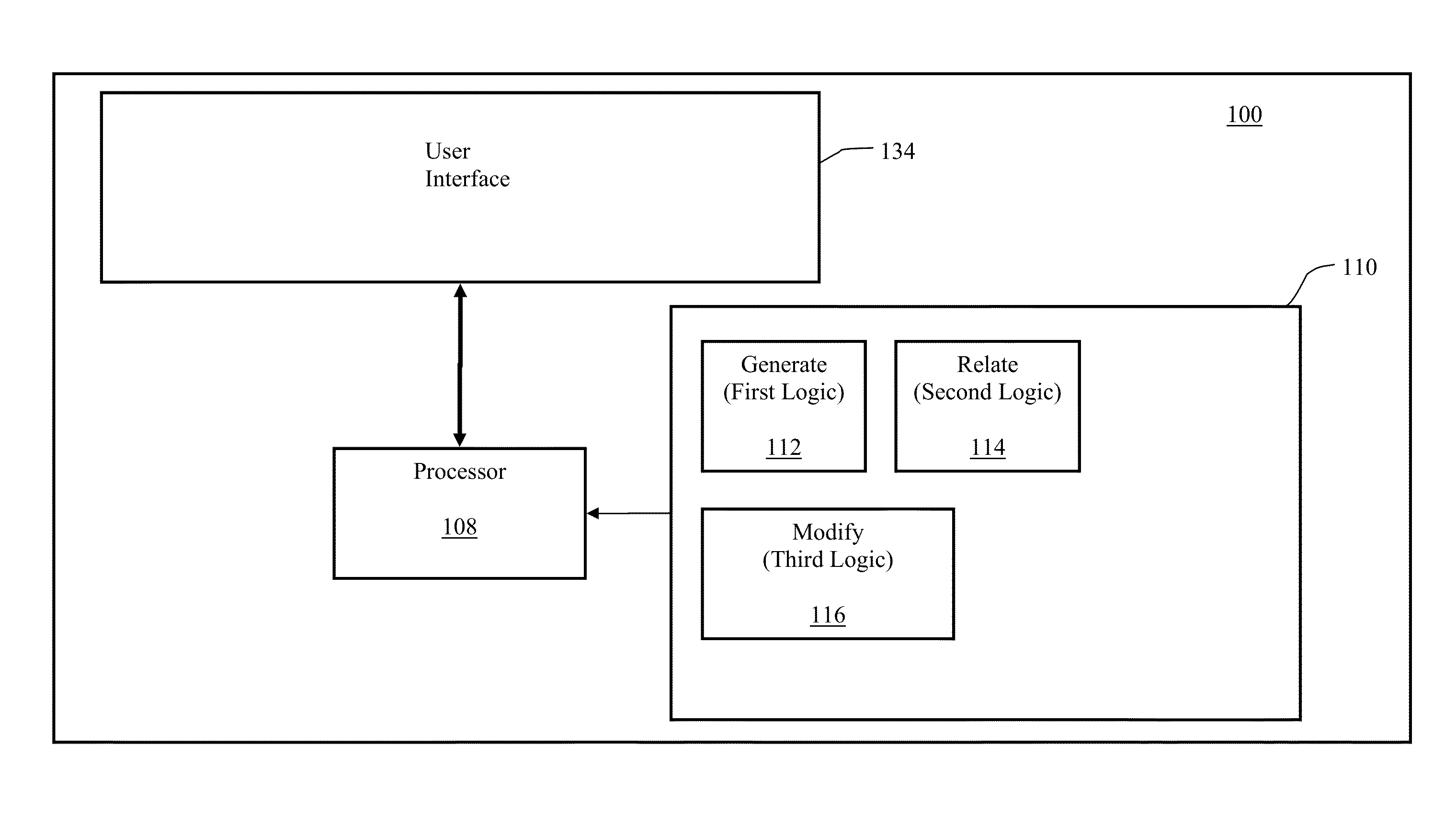
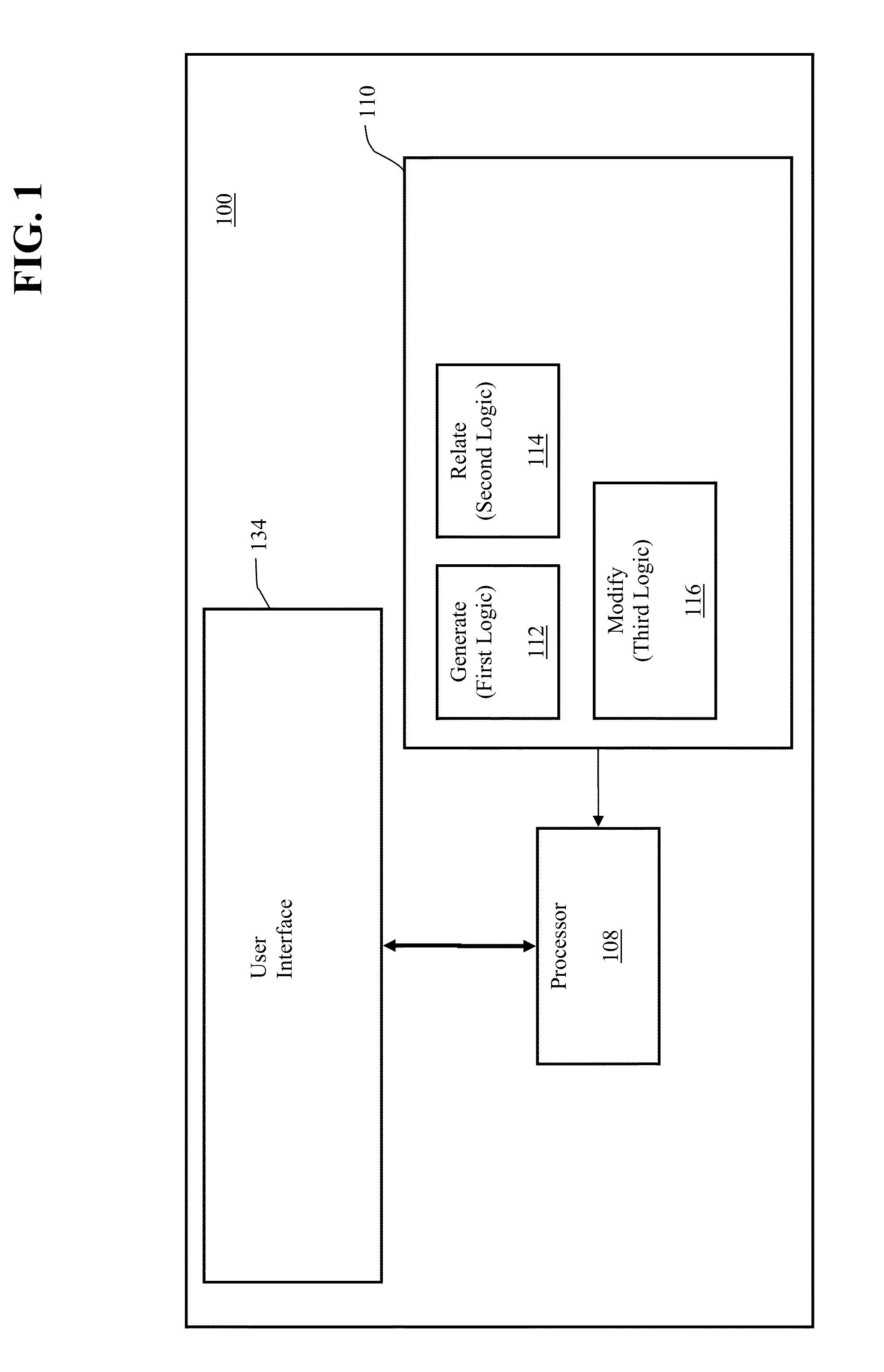
[0012]The disclosed embodiments relate to a representation of a structure or space as a collection of interrelated partitions whereby manipulation of one or more partitions causes an automated propagation of the manipulation through the other interrelated partitions as a function of the relationships therebtween. Each partition is defined by one or more vertices, the location(s) of which is / are specified either relative to an origin or relative to, i.e. as a function of, or dependent upon, the location of another vertex within the partition (intra-partition) or within another partition (inter-partition). Where the location of a vertex is moved, the change is propagated implicitly to all other vertices whose location is related, i.e. specified as a function of the modified vertex. For example, the modification of the location of an exterior wall may cause an automated propagation of that modification among the floor plans representative of the levels having the wall in common as well...


PUM


Abstract

The disclosed embodiments relate to a representation of a structure/space as a collection of interrelated partitions whereby manipulation of the partitions causes an automated propagation of the manipulation through the other interrelated partitions as a function of the relationships therebetween. Each partition is defined by one or more vertices, the location(s) of which is/are specified either relative to an origin or relative to, i.e. as a function of, or dependent upon, the location of another vertex within the partition (intra-partition) or within another partition (inter-partition). Where the location of a vertex is moved, the change is propagated implicitly to all other vertices whose location is related, i.e. specified as a function of the modified vertex.

Description

BACKGROUND[0001]A floor plan of a building, or other structure or space, is a representation or model thereof typically depicted as a view from above which may be embodied on paper or in electronic form, such as an electronic image or drawing. A floor plan defines and represents the boundary of the structure / space, referred to as the footprint, for example, as a polygon. A floor plan may further define and represent internal partitioning and / or compartmentalization of the interior, i.e. within the boundary / footprint, such as by depicting the position of walls, e.g. as lines, and other physical features. The floor plan may further represent dimensions and other absolute or relative characteristics of the structure / space through explicit notation and / or via proportional representations. Where a structure comprises multiple stories, levels or planes separating vertically defined spaces, e.g. floors, a floor plan for each floor, i.e. at each defined elevation, may be generated to depict...

Claims


Application Information

Patent Timeline
IPC IPC(8): G06F17/50
CPCG06F30/13B23P21/00E04B1/343E04B2/82
Inventor LANDES, PAUL
Owner HERE GLOBAL BV
Why Eureka
Try Eureka