

Airbag arrangement for seats arranged in tandem
- Summary
- Abstract
- Description
- Claims
- Application Information
AI Technical Summary
Benefits of technology
Problems solved by technology
Method used
Image

Examples
Embodiment Construction
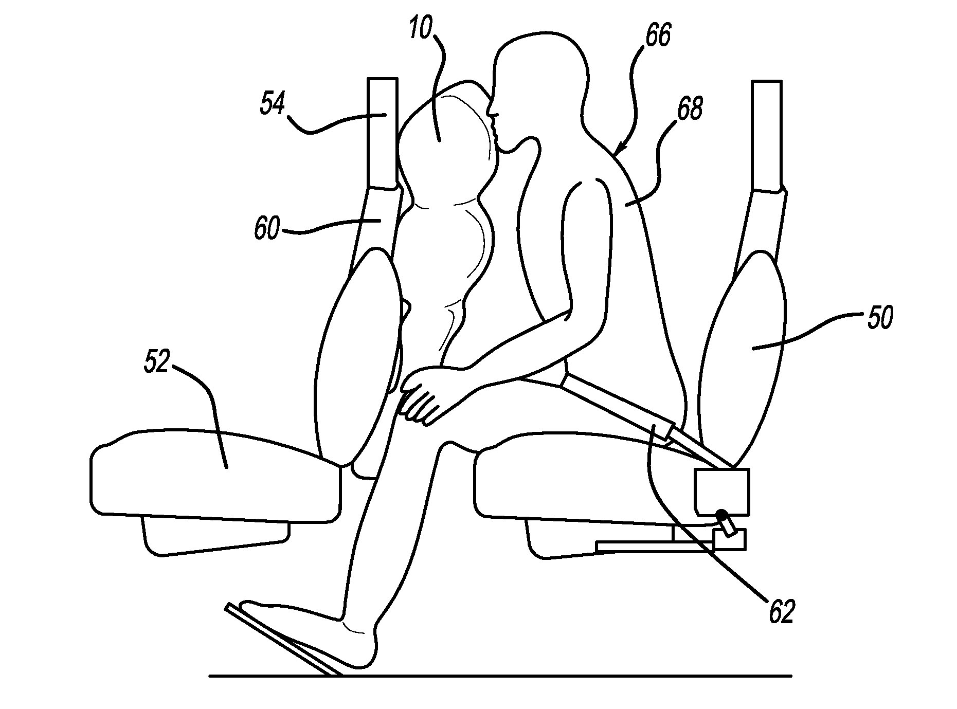
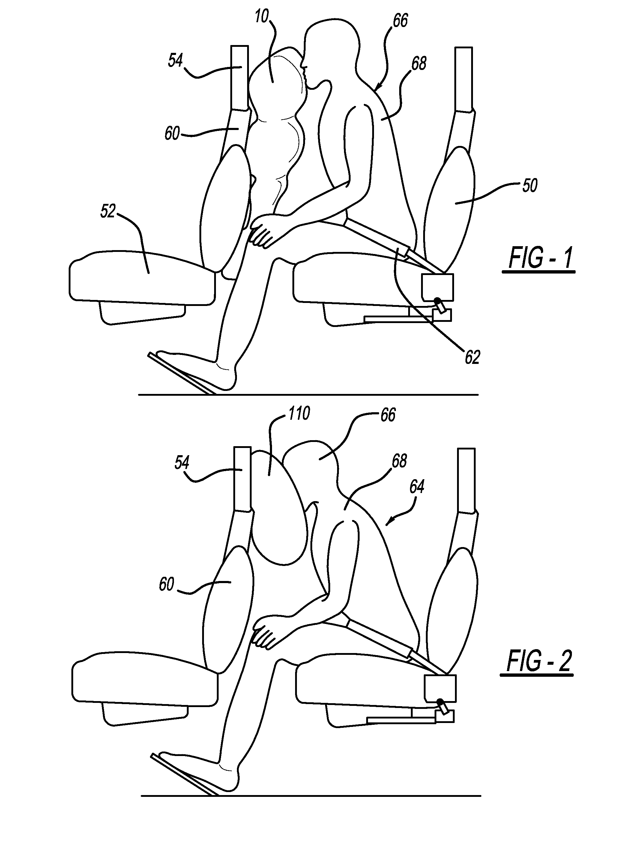
[0020]FIG. 1 shows a first aircraft seat 50 located behind a second aircraft seat 52. The seat 50 features a lap belt 62 securing a seat occupant 64 in the seat 50. After a frontal impact or large longitudinal deceleration of the aircraft, the head 66 and the upper torso 68 of the seat occupant 64 are thrown forward relative to the aircraft by inertia, causing the head 66 and upper torso 68 to move to the front and around the lap belt 62 that produces a hinging motion.
[0021]The seat back 60 of the front seat 52 includes an airbag 10 that is inflated toward the seat occupant 64 during a deceleration event before the head 66 has engaged the seat back 60. Accordingly, the head 66 contacts the inflated airbag 10 instead of continuing to move downward. The head 66 and the upper torso 68 retain an angle between each other that reduces the risk of neck injuries compared to a situation with a bare seat back 60. In the embodiment of FIG. 1, the airbag 10 is mounted in the lower half of the s...
PUM
 Abstract
Description
Claims
Application Information