Visual monitoring, or imaging, system and method for using same

a technology of visual monitoring and imaging, applied in the field of visual monitoring or imaging, system and method for using same, can solve the problems of increasing the threat to optical components, limited to single-pass welding, and inability to replace the vision of weldingers

Inactive Publication Date: 2013-12-26
BWXT NUCLEAR OPERATIONS GRP
View PDF6 Cites 32 Cited by
  • Summary
  • Abstract
  • Description
  • Claims
  • Application Information

AI Technical Summary

Benefits of technology

The present invention is about a system and method for monitoring objects that are obscured by high intensity light sources such as plasma, flame, or welding arc. The system includes a digital camera, at least one LED light source, and at least one filter. The filter can be a notch filter, a neutral density filter, or a combination of both. The system also includes software to process and interpret the data captured by the visual monitoring system. The technical effect of this invention is to provide a reliable and effective way to monitor objects in high-intensity light environments.

Problems solved by technology

The technical problem addressed in this patent is the safe and effective visual monitoring of welding operations without the risk of injury to operators caused by high intensity light sources like xenon flash lamps or lasers. Current methods require expensive and potentially unsafe equipment, including large screens and cameras, and often struggle to capture images due to unwanted reflections of the light. A new system and method are needed to allow for real-time monitoring of events involving high intensity light sources without requiring costly components or compromising operational security.

Method used


Image

  • Visual monitoring, or imaging, system and method for using same
  • Visual monitoring, or imaging, system and method for using same
  • Visual monitoring, or imaging, system and method for using same

Examples


Embodiment Construction

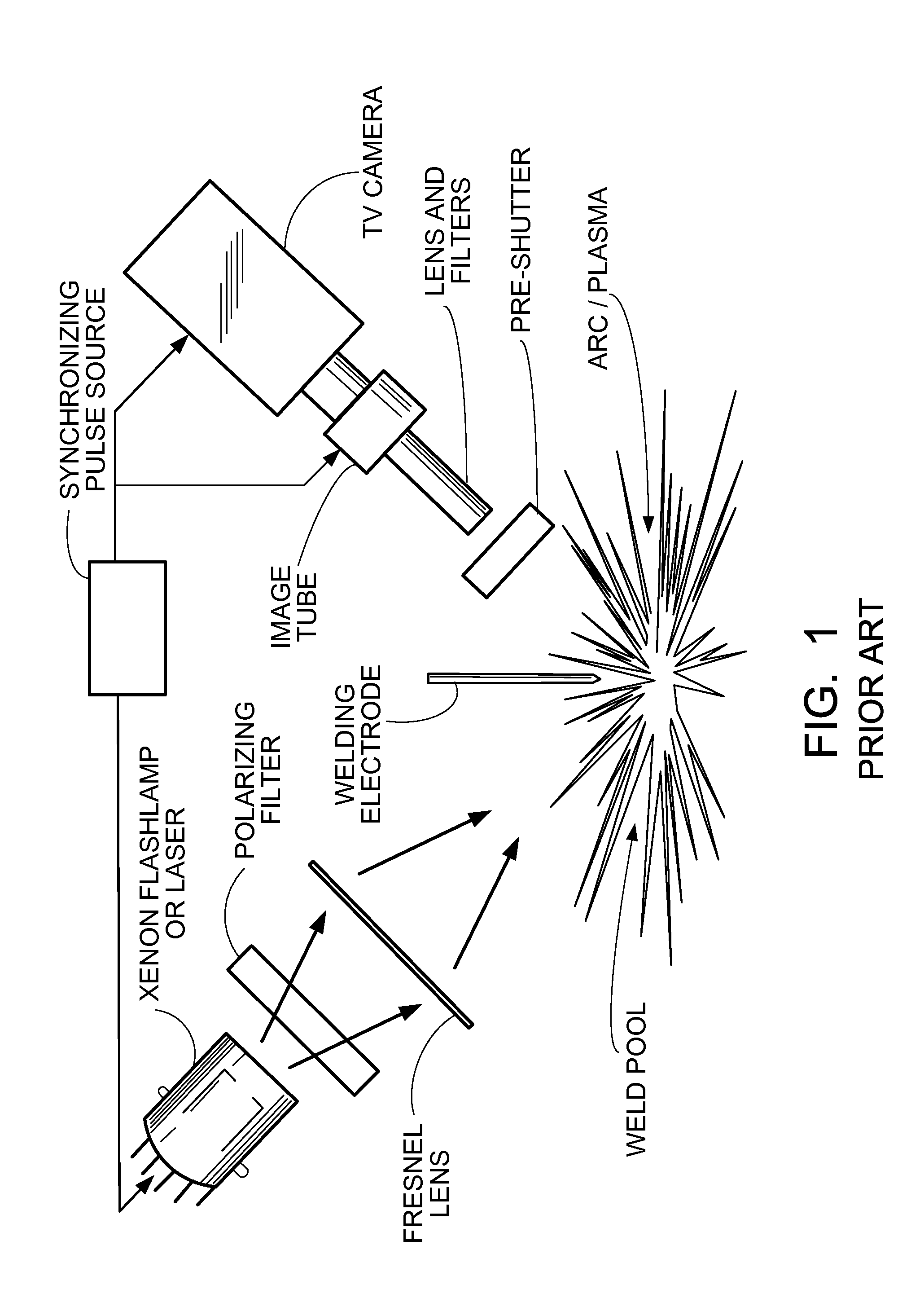
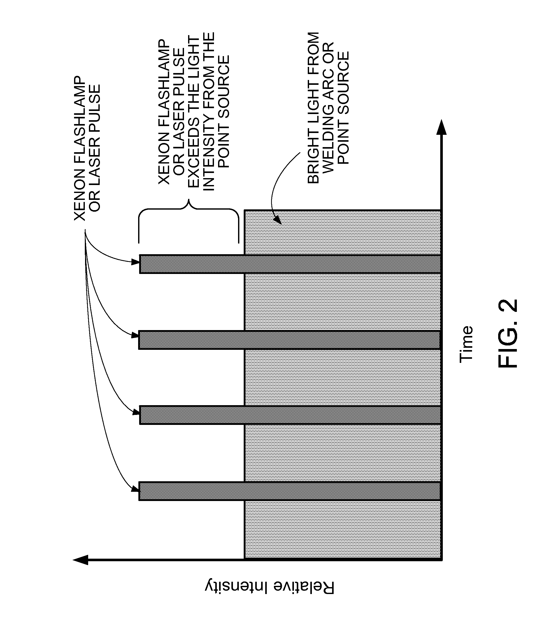
[0048]While the present invention will be described in terms of a visual monitoring, or imaging, system and method for use in conjunction with a plasma welding process, flame-based welding process, or a welding arc process, the present invention is not limited thereto. Rather, the system and / or method of the present invention can be utilized in any situation where the need presents itself to visually monitor, or image, any process that is, or may be, obscured by a high intensity light source.

[0049]Thus, as stated above, the present invention relates generally to both a system and method for visually (e.g., via a video-based system or some other visual system) monitoring one or more objects where such objects are obscured by a high intensity light source such as a plasma, flame, or welding arc. In one embodiment, a system in accordance with the present invention comprises a digital camera, at least one light emitting diode (LED) light source, and at least one filter. In another embod...


PUM


Abstract

The present invention relates generally to both a system and method for visually (e.g., via a video-based system or some other visual system) monitoring one or more objects where such objects are obscured by a high intensity light source such as a plasma, flame, or welding arc. In one embodiment, a system in accordance with the present invention comprises a digital camera, at least one light emitting diode (LED) light source, and at least one filter. In another embodiment, a system in accordance with the present invention comprises a digital camera, at least one light emitting diode (LED) light source, and at least one filter selected from a notch filter, a neutral density filter, or combinations thereof. Additionally, the system of the present invention can further include software designed to process, interpret and/or collect various data captured by the visual monitoring, or, imaging, system of the present invention.

Description


Claims


Application Information

Patent Timeline
Owner BWXT NUCLEAR OPERATIONS GRP
Why Eureka
Try Eureka