Narrow profile catheter with deformation-resistive guidewire lumen

Inactive Publication Date: 2013-12-26
ACROSTAK CORP
View PDF22 Cites 21 Cited by
  • Summary
  • Abstract
  • Description
  • Claims
  • Application Information

AI Technical Summary

Benefits of technology

[0010]an inner lumen (57), for the passage of fluidic substance or guidewire, disposed within the inflation lumen (36) and fluidicly isolated therefrom, wherein at least part of the wall (39) of the inner lumen (57) is m

Problems solved by technology

It is a problem in the art that, some regions of vessels such as the distal peripher

Method used


Image

  • Narrow profile catheter with deformation-resistive guidewire lumen
  • Narrow profile catheter with deformation-resistive guidewire lumen
  • Narrow profile catheter with deformation-resistive guidewire lumen

Examples


Embodiment Construction

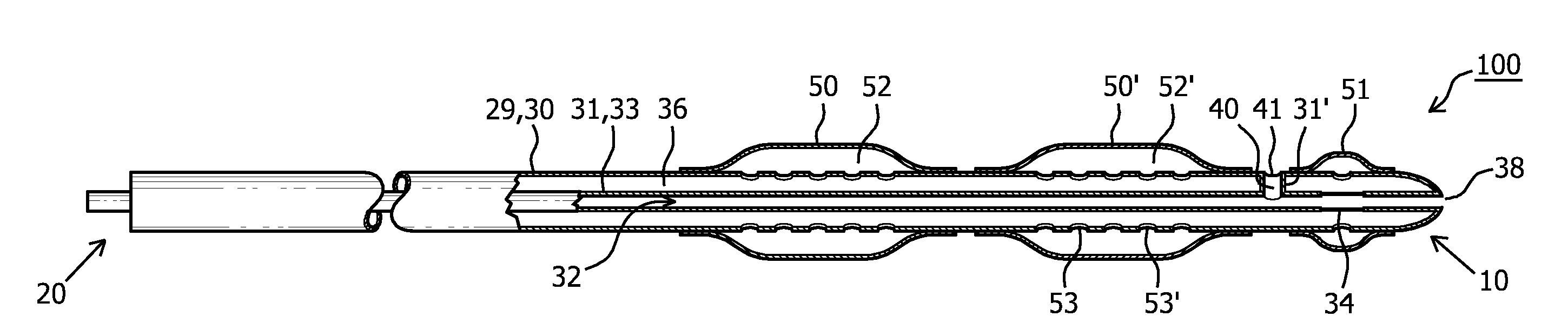
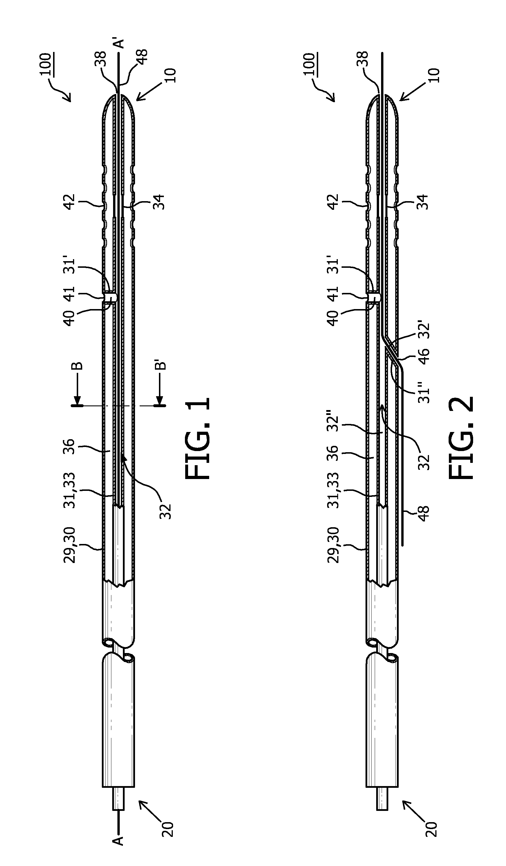
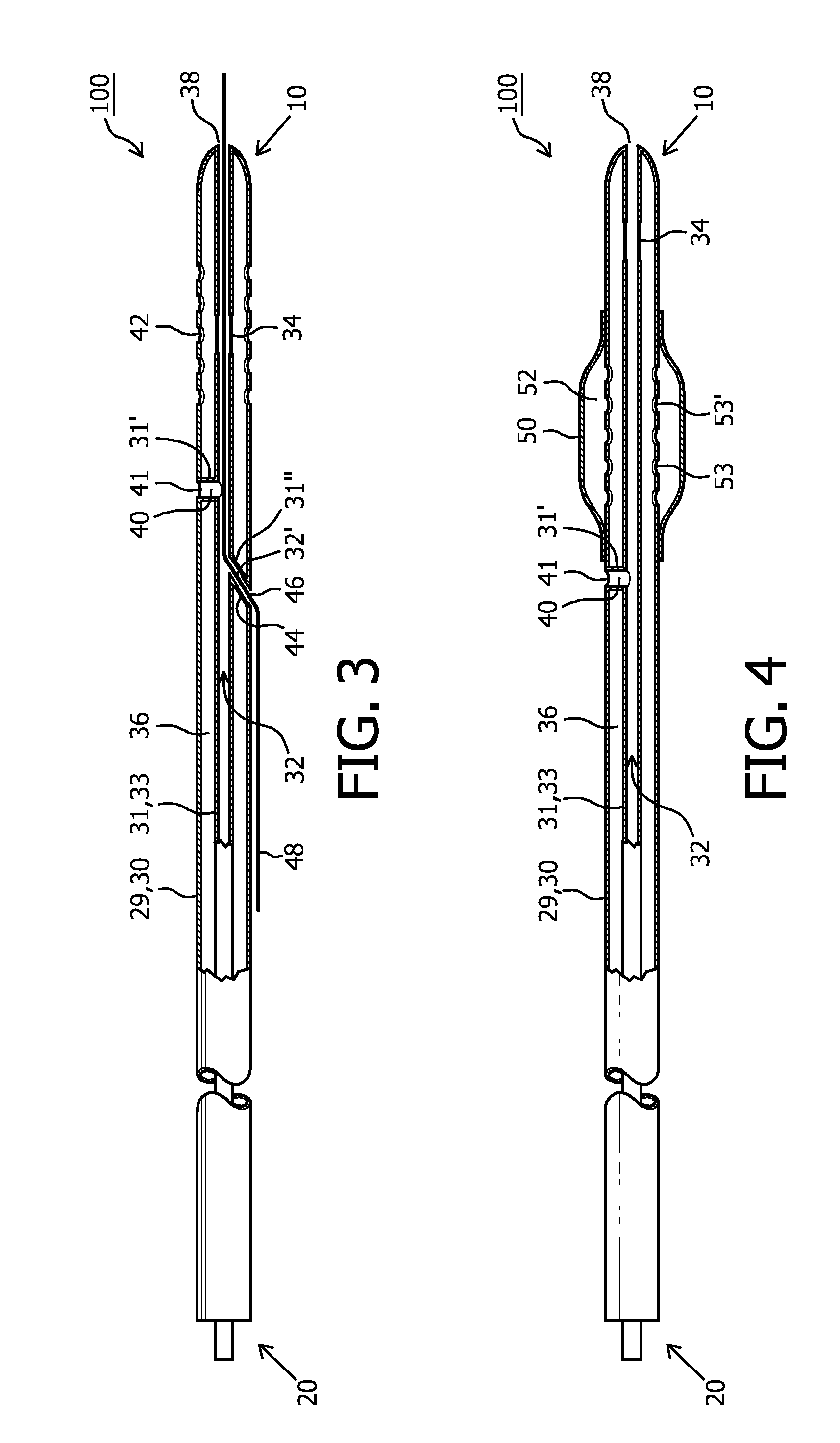
[0008]One embodiment of the invention relates to a catheter (100) having a proximal end (20) and distal end (10), comprising:[0009]an elongated longitudinal shaft (30), which forms the outer wall of an inflation lumen (36) extending from the proximal (20) end towards the distal (10) end of the shaft (30), and[0010]an inner lumen (57), for the passage of fluidic substance or guidewire, disposed within the inflation lumen (36) and fluidicly isolated therefrom, wherein at least part of the wall (39) of the inner lumen (57) is made from tubing (8) reinforced with a helically coiled wire (12) or helically braided wire (14) having a helix angle of 60 degrees or more which tubing is resistive to radial pressure applied in the inflation lumen (36).

[0011]The shaft (30) may comprise at least one inflatable balloon (50) at the distal end (10), the inflation lumen (36) being in fluidic connection with a balloon lumen (52).

[0012]The wall (39) of the inner lumen (57) may comprise two regions of t...


PUM


Abstract

The present disclosure relates to a catheter having a longitudinal guidewire lumen defined by a first tube configured for an over-the-wire or rapid-exchange mode of operation, the wall of the first tube provided with an expansion member that is a sub-region of the wall of the first tube provided with an expandable material. An inflation lumen extending from the proximal end towards the distal end of the shaft is in fluidic contact with the expansion member, the member being configured to expand or contract responsive to pressure in the inflation lumen. The wall of the first tube may be formed from a helically coiled wire or helically braided wire having a helix angle of 60 degrees or more which tubing is resistive to radial pressure applied in the inflation lumen.

Description

FIELD OF THE INVENTION[0001]This invention relates to a catheter having a narrow profile suited for advancement through the vasculature over a guidewire in an over-the-wire or rapid-exchange mode of operation. More particularly, the invention relates an adaptation of the guidewire lumen to controllable release fluid, which release is modulated by an inflatable member adapted for switchable occlusion of the guidewire lumen. The guidewire lumen has a dual function, reducing the number of required lumens, and concomitantly, the profile of the catheter.BACKGROUND TO THE INVENTION[0002]The use of catheters to treat structures, stenoses, or narrowings in various parts of the human body is well known in the prior art. Examples of such catheters are given in Bonzel U.S. Pat. No. 4,762,129, Yock U.S. Pat. No. 5,040,548, Kanesaka U.S. Pat. No. 5,330,499, Solar U.S. Pat. No. 5,413,557, and Tsukashima et al. U.S. Pat. No. 5,458,639.[0003]In many cases, it is usual practice to advance a guidewir...

Claims


Application Information

Patent Timeline
IPC IPC(8): A61M25/10A61F2/958
CPCA61M25/10A61M25/1011A61M25/003A61M25/0032A61M25/0053A61M25/007A61M25/0097A61M25/1002A61M2025/0018A61M2025/0035A61M2025/0039A61M2025/0183A61M2025/09125A61M2025/1061
Inventor BERGER, ERWINPOPOWSKI, YOURI
Owner ACROSTAK CORP
Why Eureka
Try Eureka