Grid runner to perimeter trim clip

a technology for perimeter trim and clip, which is applied in the direction of building reinforcements, construction, building components, etc., can solve the problems of screw cross-threading risk, the added cost of assembly, and the deformation of the trim strip, so as to facilitate the assembly of trim quickly, and reduce the risk of screw cross-threading

Inactive Publication Date: 2014-01-02
USG INTERIORS INC
View PDF4 Cites 19 Cited by
  • Summary
  • Abstract
  • Description
  • Claims
  • Application Information

AI Technical Summary

Benefits of technology

[0006]The disclosed clip, by avoiding the need for separate clip parts and fasteners, facilitates rapid assembly of the trim on the grid runners. Moreover, the clip installation requires minimal dexterity and skill to obtain high quality fit and finish.

Problems solved by technology

This prior art clip and other known design which have a set screw to locate the trim in place can create a problem if the screw is over-tightened causing the trim strip to be permanently deformed.
The types of clips incorporating set screws have the added cost of their separate parts and their assembly.
There is a risk that the screw can be cross-threaded, particularly if it is assembled by the ceiling grid installer.
Moreover, there is a potential problem that the clip parts can be dropped by the installer who is trying to hold and align several elements together at the same time and trying to tighten a screw.

Method used


Image

  • Grid runner to perimeter trim clip
  • Grid runner to perimeter trim clip
  • Grid runner to perimeter trim clip

Examples


Embodiment Construction

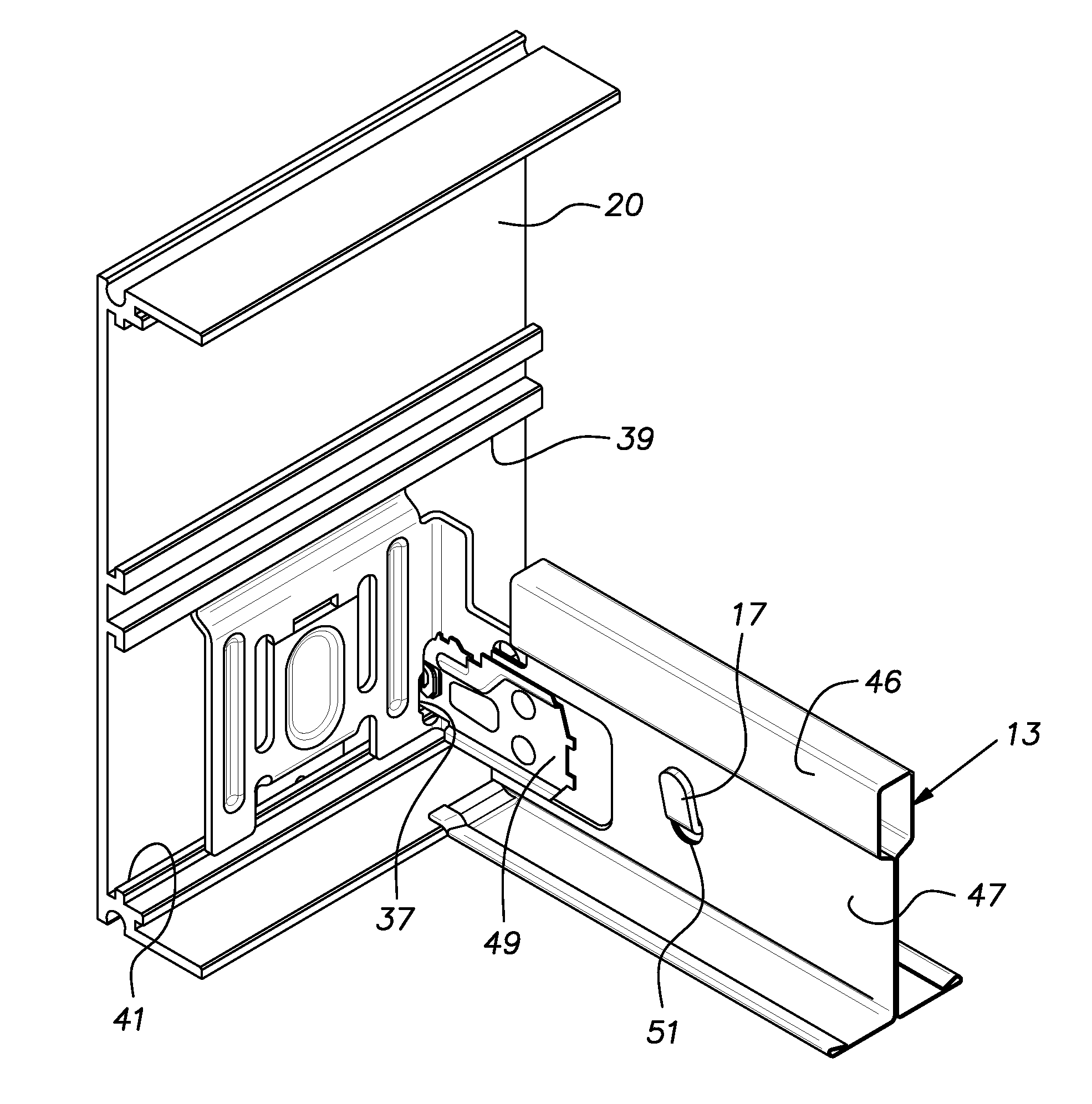
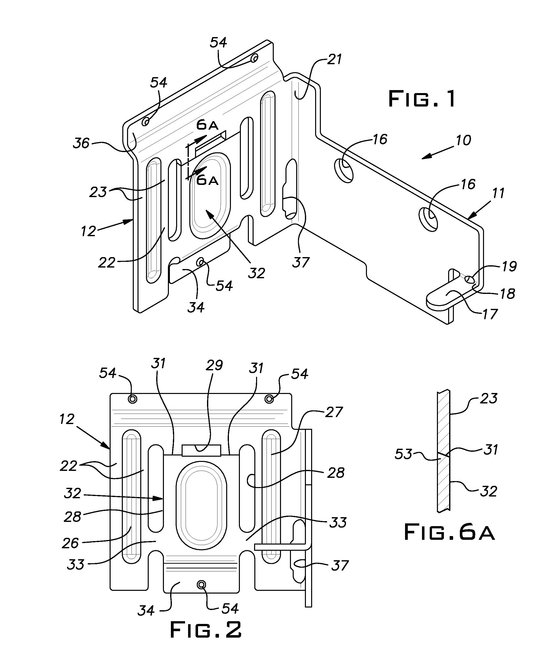
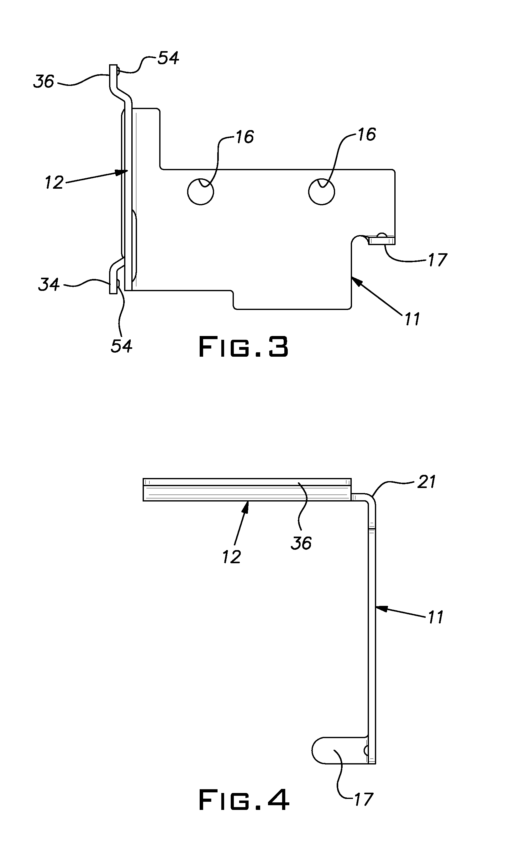
[0015]A clip 10 embodying the invention has the general shape of a right angle bracket with perpendicular legs 11, 12. The clip 10 is shown, other than in FIG. 4, in its upright in-use orientation. The clip 10, preferably, is a rigid, one-piece stamping of sheet metal, for example, of 0.048 in. thick hot dipped galvanized steel. A first one 11 of the legs is adapted to be joined with a grid runner 13. The leg 11 is generally planar, with a pair of horizontally spaced holes 16 for receiving optional screws or rivets. At a distal end of the leg 11, there is formed a relatively narrow tab 17 extending horizontally from a horizontal bend line 18. A hole 19 interrupts the bend line 18 to facilitate manual bending of the tab 17 during installation of the clip 10.

[0016]The legs 11, 12 are joined at a vertical corner 21. The leg 12 is adapted to connect an elongated trim strip 20 of known construction that conceals the ends of laterally spaced parallel grid runners 13 and ceiling tiles at t...


PUM


Abstract

A clip for mounting an elongated trim strip on ends of ceiling grid runners, having a right angle configuration with two intersecting legs, one leg adapted to laterally abut an end of a grid runner and the other being adapted to engage the trim strip, said other leg having oppositely extending upper and lower grips for reception into upper and lower opposing channels of the trim strip, the grips being relatively moveable, and a toggle arrangement for moving said grips away from one another, when retracted, the grips being capable of passing between the opposed channels, the toggle arrangement selectively maintaining said grips in an extended position to frictionally lock onto the opposed channels of the trim strip.

Description

BACKGROUND OF THE INVENTION[0001]The invention relates to suspended ceiling systems and, in particular, to accessories for mounting ceiling edge trim.PRIOR ART[0002]Suspended ceiling islands and soffits are frequently finished at their perimeter or edge with an elongated trim strip to conceal the ends of the suspended grid runners and edges of the tile and to obtain a desired visual effect. Clips or brackets have been devised to connect the ends of the grid runners to the trim strip. U.S. Pat. Nos. 4,744,188; 5,195,289; 5,201,787; and 7,930,864 disclose examples of prior art clips developed for this purpose. The clip shown in the last mentioned '864 patent is an example of a product intended to connect with trim strips having mounting channels on their concealed sides. This prior art clip and other known design which have a set screw to locate the trim in place can create a problem if the screw is over-tightened causing the trim strip to be permanently deformed. Another known type o...

Claims


Application Information

Patent Timeline
Patent Type & Authority Applications(United States)
IPC IPC(8): E04B9/18E04B1/38
CPCE04B9/127E04B9/30E04B1/38E04B9/18
Inventor UNDERKOFLER, ABRAHAM M.PAULSEN, MARK R.GULBRANDSEN, PEDER J.
Owner USG INTERIORS INC
Why Eureka
Try Eureka