Exhaust-gas heat exchanger

Inactive Publication Date: 2014-01-02
BEHR GMBH & CO KG
View PDF11 Cites 6 Cited by
  • Summary
  • Abstract
  • Description
  • Claims
  • Application Information

AI Technical Summary

Benefits of technology

The patent text describes a design where a flange is formed in one piece with the housing of an exhaust-gas heat exchanger. This flange allows for direct connection to components upstream or downstream of the heat exchanger. The technical effect of this design is that it saves costs and working steps by eliminating the need for additional components to attach the flange to the housing or diffuser.

Problems solved by technology

A disadvantage of the prior art is in particular the fact that the flange constitutes an additional component, resulting in increased costs for parts.
Furthermore, the joining of the flange to the heat exchanger constitutes an additional process step which increases the machining time and entails additional costs.
The high exhaust-gas temperatures could otherwise lead to permanent deformation or to failure of individual components.

Method used


Image

  • Exhaust-gas heat exchanger
  • Exhaust-gas heat exchanger

Examples


Embodiment Construction

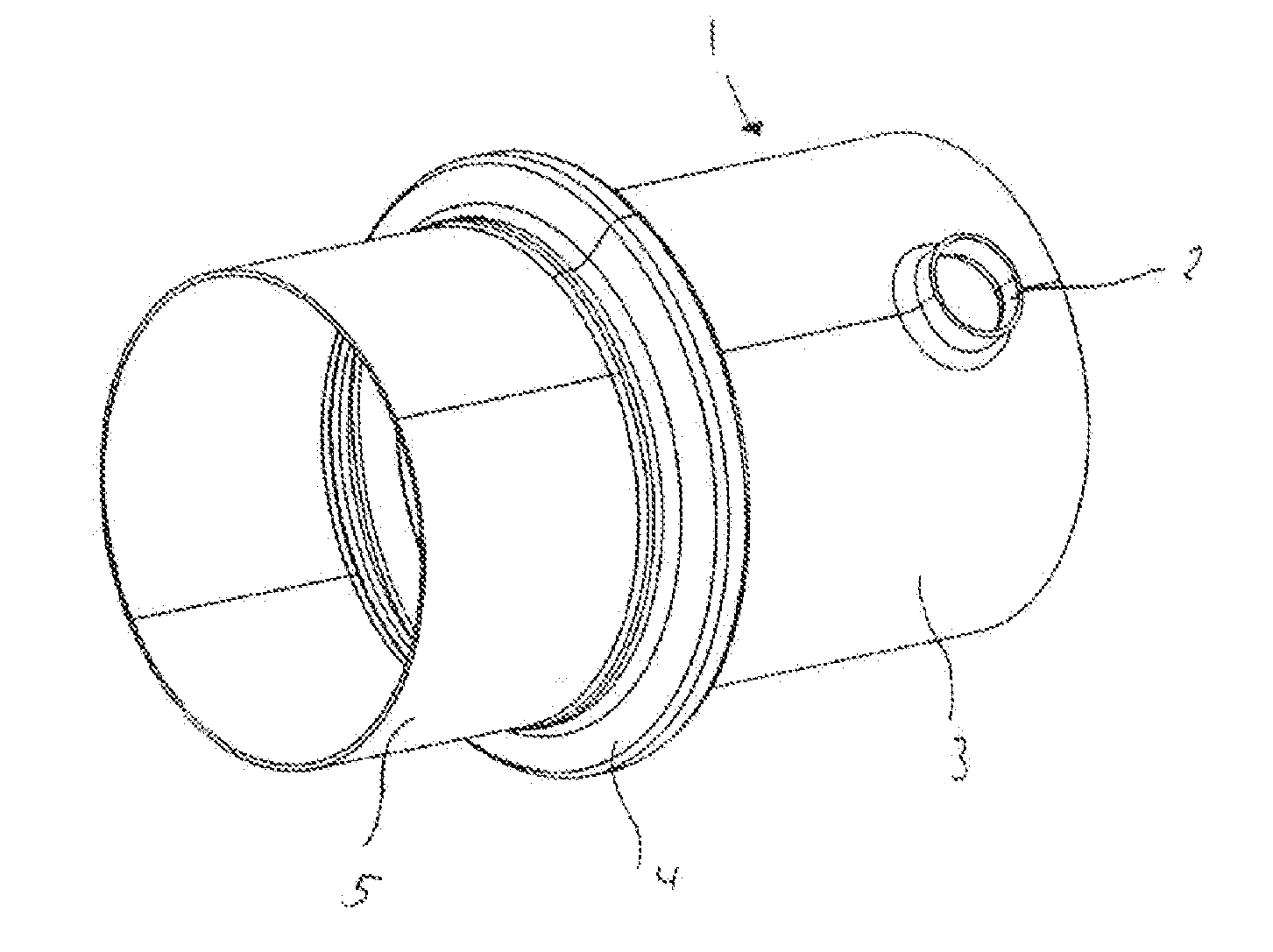
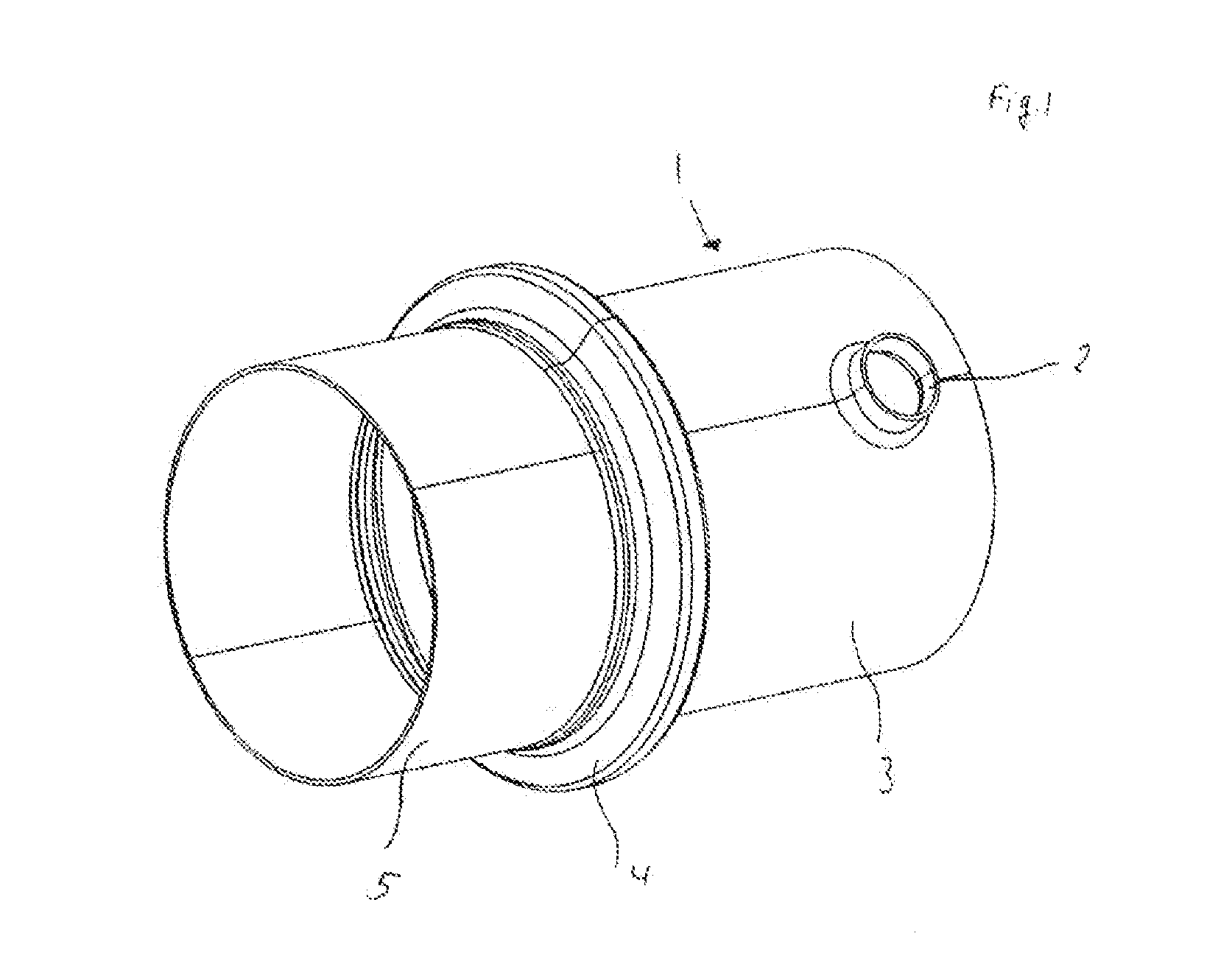
[0024]FIG. 1 shows a perspective view of an exhaust-gas heat exchanger 1. The exhaust-gas heat exchanger 1 is composed substantially of a housing 3 which, in the interior, has a multiplicity of flow ducts which, in their end regions, are received in tube plates. The tube plates and the flow ducts cannot be seen in FIG. 1 owing to the perspective view.

[0025]The housing 3 surrounds the tube plates in such a way that a second flow duct is formed which is separated from the flow ducts enclosed in the tube plates. A fluid can flow into the housing via the fluid inlet 2 and can flow through said housing. Not illustrated in FIG. 1 is the fluid outlet through which the fluid can exit the housing 3 again.

[0026]A further fluid, preferably the exhaust gas in an exhaust tract, flows through the exhaust-gas heat exchanger 1 along the flow ducts enclosed in the tube plates. A second fluid flows through said exhaust-gas heat exchanger through the fluid inlet 2 and the fluid outlet (not shown), whe...


PUM


Abstract

An exhaust-gas heat exchange, in particular for use in the exhaust tract of a motor vehicle, having a housing and having a first flow duct through which a first fluid can flow and which is received at its end regions in tube plates, wherein the first flow duct and the tube plates are surrounded by the housing in such a way that the housing forms a second flow duct through which a second fluid can flow, which second fluid can flow around the first flow duct, having a first diffuser which conducts the first fluid into the first flow duct and having a second diffuser which conducts the first fluid out of the first flow duct, characterized in that the exhaust-gas heat exchanger has, at at least one of its end regions, an at least partially encircling first flange which is formed in one piece with the exhaust-gas heat exchanger.

Description

TECHNICAL FIELD[0001]An exhaust-gas heat exchanger, in particular for use in the exhaust tract of a motor vehicle, having a housing and having a first flow duct through which a first fluid can flow and which is received at its end regions in tube plates, wherein the first flow duct and the tube plates are surrounded by the housing in such a way that the housing forms a second flow duct through which a second fluid can flow, which second fluid can flow around the first flow duct, having a first diffuser which conducts the first fluid into the first flow duct and having a second diffuser which conducts the first fluid out of the first flow duct.PRIOR ART[0002]Exhaust-gas heat exchangers are preferably used in motor vehicles, where they are arranged downstream of the internal combustion engine. The hot exhaust gas discharged by the internal combustion engine is cooled in said exhaust-gas heat exchangers and can be supplied back to the internal combustion engine by means of exhaust-gas ...

Claims


Application Information

Patent Timeline
IPC IPC(8): F28F1/00
CPCF28F1/00F28F9/00F01N2240/02F28D21/0003F02M26/32Y10T29/49362B23P15/26
Inventor SIEGEL, ALBRECHTFABER, CHRISTIANHUND, SIMON
Owner BEHR GMBH & CO KG
Why Eureka
Try Eureka