Filament cutterhead for a brushcutter

Active Publication Date: 2015-10-29
ANDREAS STIHL AG & CO KG
View PDF9 Cites 4 Cited by
  • Summary
  • Abstract
  • Description
  • Claims
  • Application Information

AI Technical Summary

Benefits of technology

[0012]A simple configuration results when the shield element is a shield wall. In order to avoid the accumulation of soiled material on the filament cutterhead, it is advantageously provided that the peripheral wall, which radially defines the inner region to the outside relative to the rotational axis, widens in at least one portion in the direction of the plane of the lower face of the base body. As a result, it is facilitated that soiled material which has accumulated in the inner region is conducted by the action of centrifugal force from the peripheral wall out of the inner region and may be projected downwardly out of the filament cutterhead. Particularly advantageously, the peripheral wall advantageously widens in at least one portion adjacent to the lower face. Advantageously, the cross section of the inner region is circular and the diameter of the inner region, measured perpendicular to the rotational axis, increases in the at least one portion in which the peripheral wall widens, in the direction of the plane of the lower face of the base body. Advantageously, the diameter of the inner region on the lower face of the base body is at least approximately 120%, preferably at least approximately 130%, of the diameter of the inner region on the lower edge of the shield element facing the lower face of the base body. As a result, a relatively large opening of the inner region is produced at the bottom which prevents the accumulation of soiled material in the inner region and encourages soiled material to drop off downward. The peripheral wall is advantageously configured in the at least one portion as a cone portion, wherein the cone widens toward the lower face. Soiled material in the inner region is moved radially outwardly during operation relative to the rotational axis due to the centrifugal force. The effect of the cone shape of the peripheral wall is that soiled material, which is moved outwardly due to the centrifugal force, is conducted downwardly ou

Problems solved by technology

Soiled material on the filament cutterhead may cause an imbalance of the fil

Method used


Image

  • Filament cutterhead for a brushcutter
  • Filament cutterhead for a brushcutter
  • Filament cutterhead for a brushcutter

Examples


Example

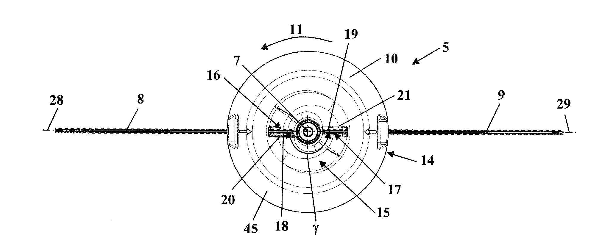
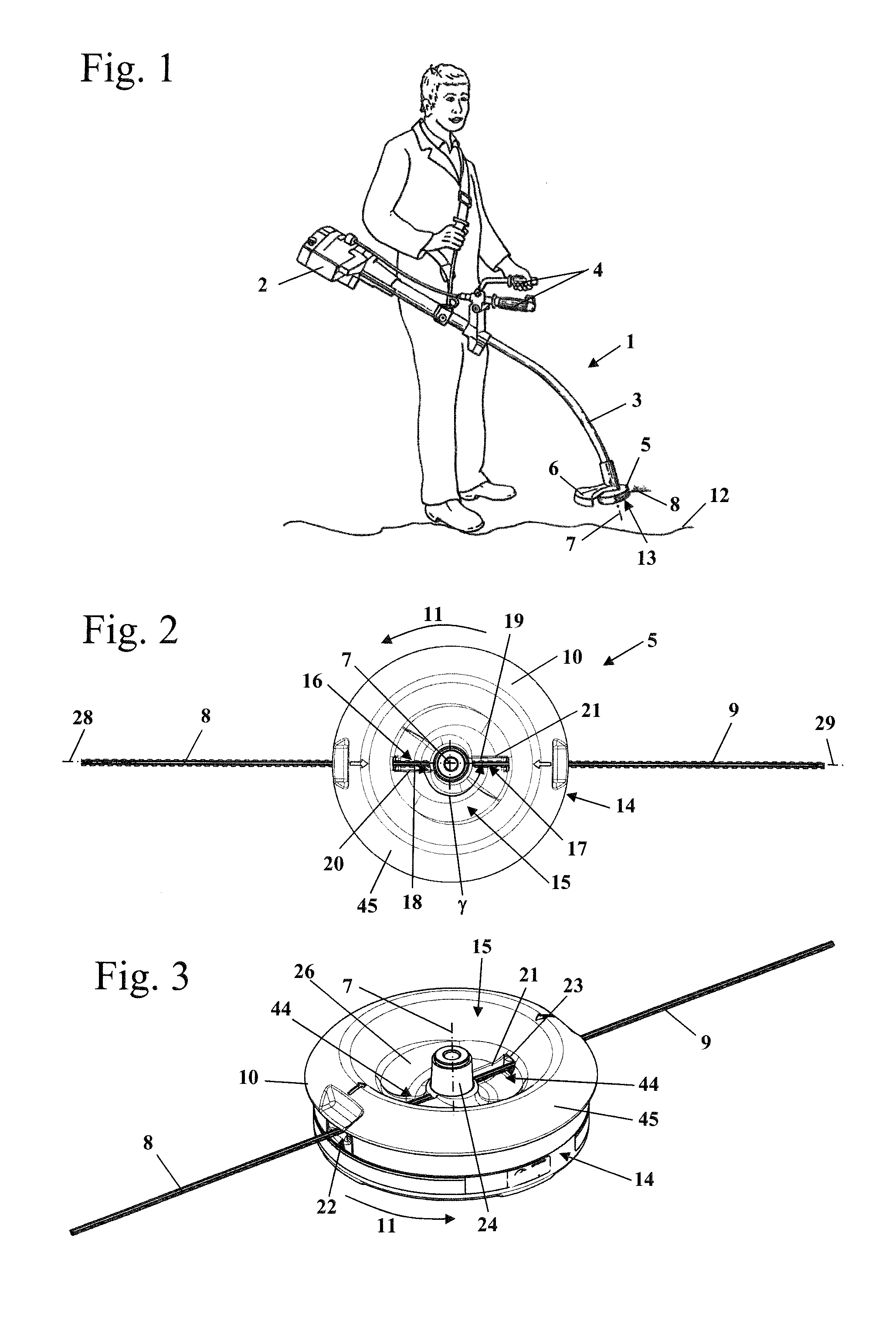
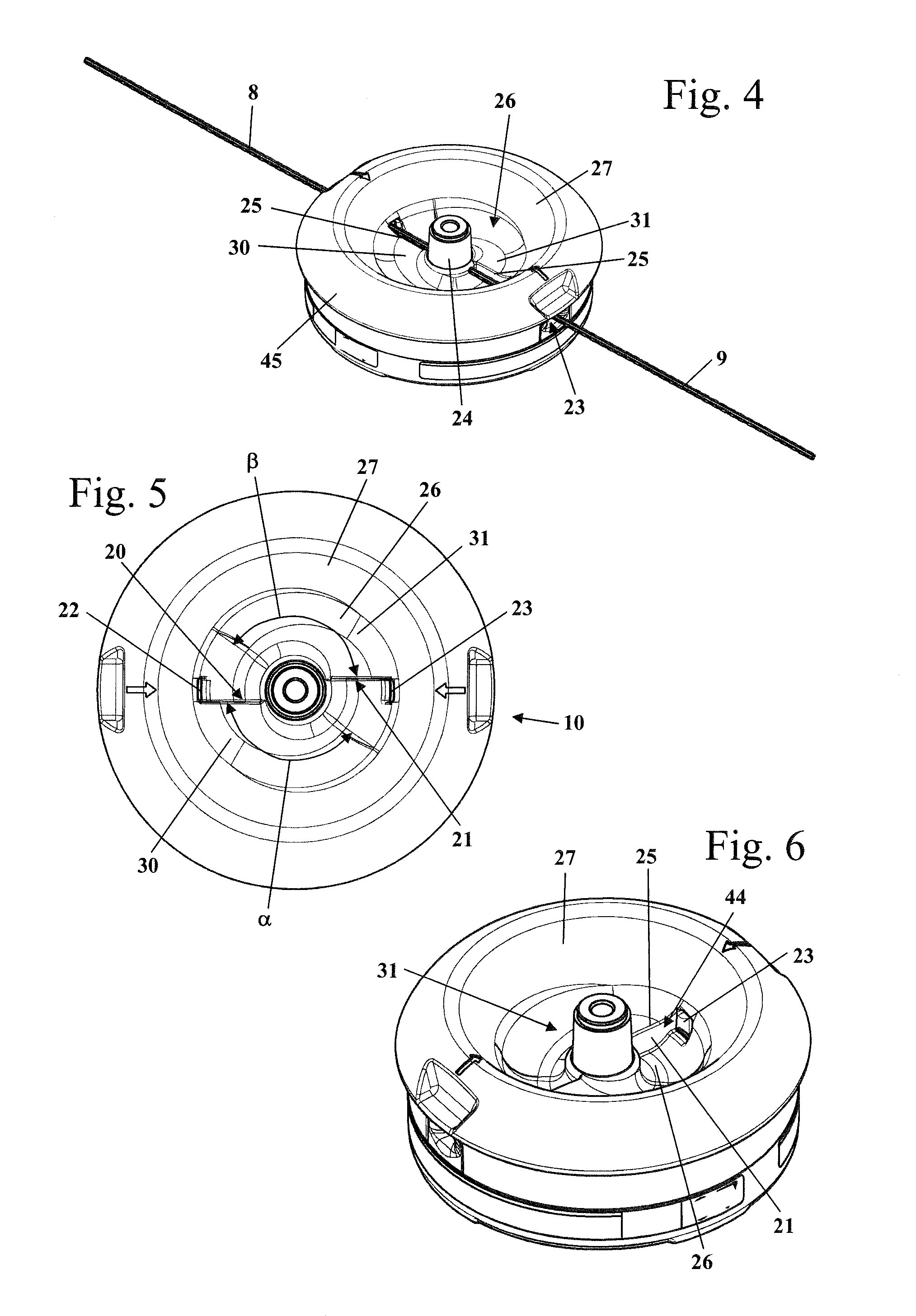
[0033]FIG. 1 shows a brushcutter 1 which is held by an operator. The brushcutter 1 has a housing 2 in which a drive motor is arranged. The brushcutter 1 has a shaft 3 which is arranged with one end on the housing 2 and the other end thereof carries a filament cutterhead 5. A drive shaft protrudes through the shaft 3 driven by the drive motor arranged in the housing 2, the drive shaft rotatably driving the filament cutterhead 5 about a rotational axis 7. During operation, the filament cutterhead 5 is covered on the side facing the operator by a protective cover 6. The filament cutterhead 5 has a filament or cutting line 8 which serves for cutting material to be cut, such as grass, brush or the like. The filament cutterhead 5 has a lower face 13 facing the ground 12 during operation, the lower face being arranged on the side of the filament cutterhead 5 remote from the shaft 3. For guiding the brushcutter 1 during operation, handles 4 are provided, the handles being arranged in the em...


PUM


Abstract

A filament cutterhead for a brushcutter is able to be driven in a rotatable manner during operation in a rotational direction about a rotational axis. The filament cutterhead has a base body on which at least one cutting filament is retained and which has a lower face facing the ground during operation. The cutting filament extends from an outer face of the base body through an opening as far as an inner region of the base body which is open toward the lower face of the base body. In order to achieve a low degree of soiling of the filament cutterhead during operation, a shield element is provided in the inner region and the leading portion of the cutting filament in the inner region is arranged in the slipstream of the shield element relative to the rotational direction.

Description

CROSS REFERENCE TO RELATED APPLICATION[0001]This application claims priority of German patent application no. 10 2014 006 057.8, filed Apr. 26, 2014, the entire content of which is incorporated herein by reference.BACKGROUND OF THE INVENTION[0002]A filament cutterhead for a brushcutter is disclosed in U.S. Pat. No. 6,519,857, the filament cutterhead having a base body in which two cutting filaments may be inserted from opposing sides from the outer face of the filament cutterhead. The cutting filaments are retained on the filament cutterhead via pivotable pawls. The free ends of the cutting filaments protrude into an inner space which is open toward the lower face of the filament cutterhead. In order to remove the cutting filaments from the filament cutterhead, for example for replacement, the internal free ends of the cutting filaments may be gripped by the operator and the cutting filaments pulled inwardly.[0003]It has been shown that the inner region of the base body which is ope...

Claims


Application Information

Patent Timeline
IPC IPC(8): A01D34/416
CPCA01D34/4165A01D34/4167A01D34/416
Inventor GUENTHER, DAVIDHAUBER, THOMAS
Owner ANDREAS STIHL AG & CO KG
Why Eureka
Try Eureka